
Reducing log entries using hash keys

a technology of hash keys and log entries, applied in the field of reducing log entries using hash keys, can solve the problems of affecting the effective use of log entries, affecting the search effect, so as to reduce the size of the log file, the effect of small field and little storage spa

Inactive Publication Date: 2009-03-10
IBM CORP
View PDF12 Cites 48 Cited by
  • Summary
  • Abstract
  • Description
  • Claims
  • Application Information

AI Technical Summary

Benefits of technology

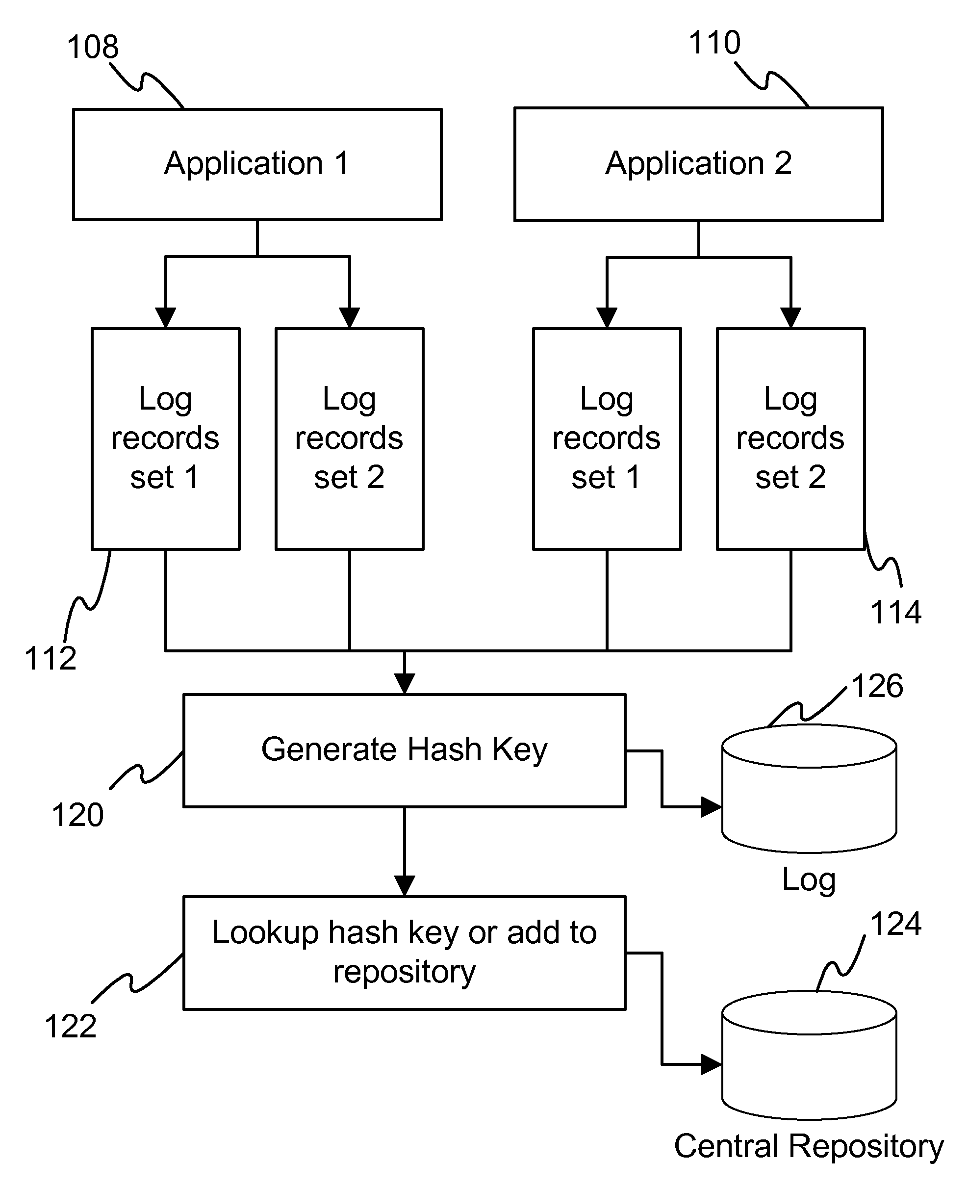
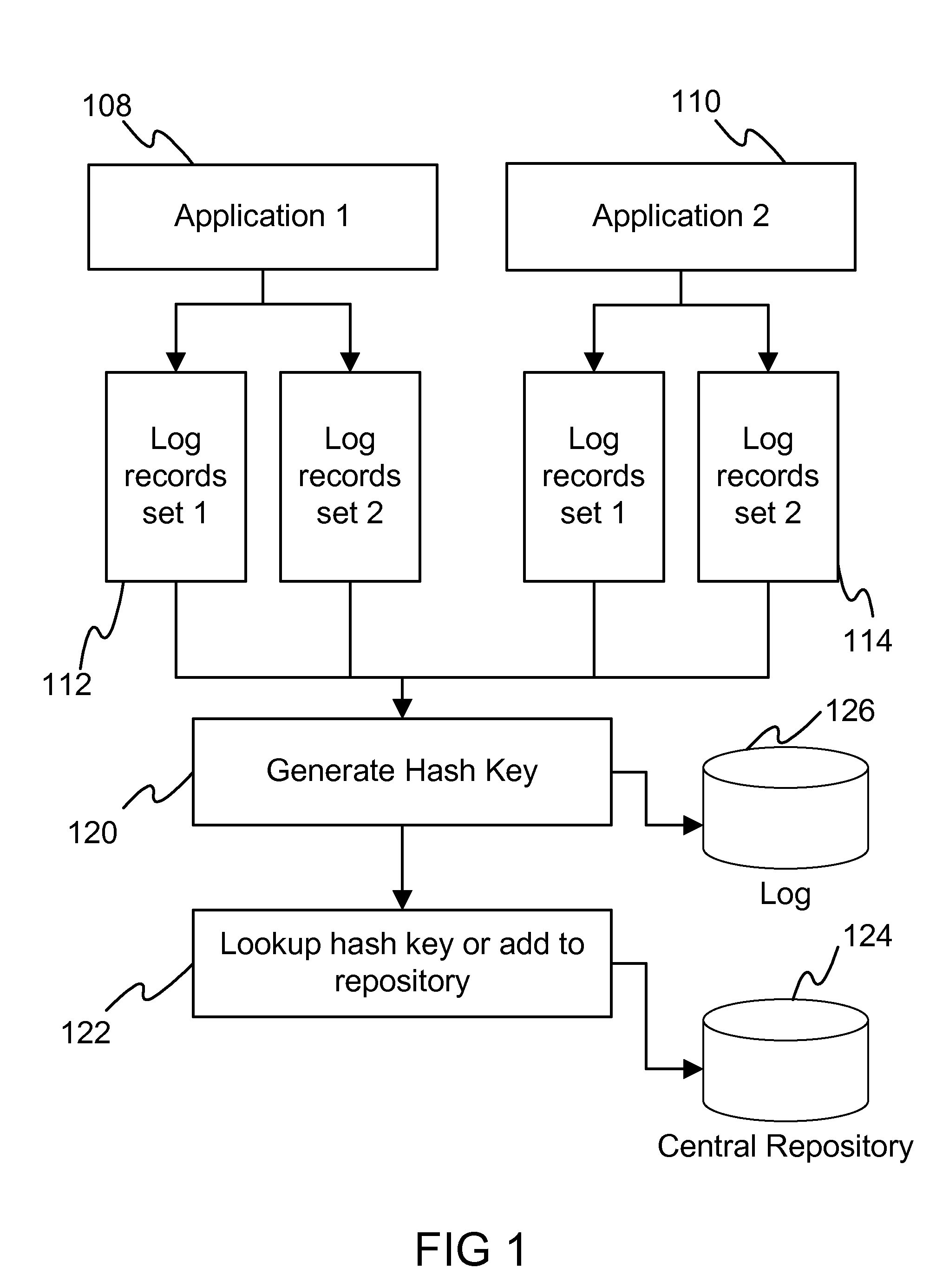
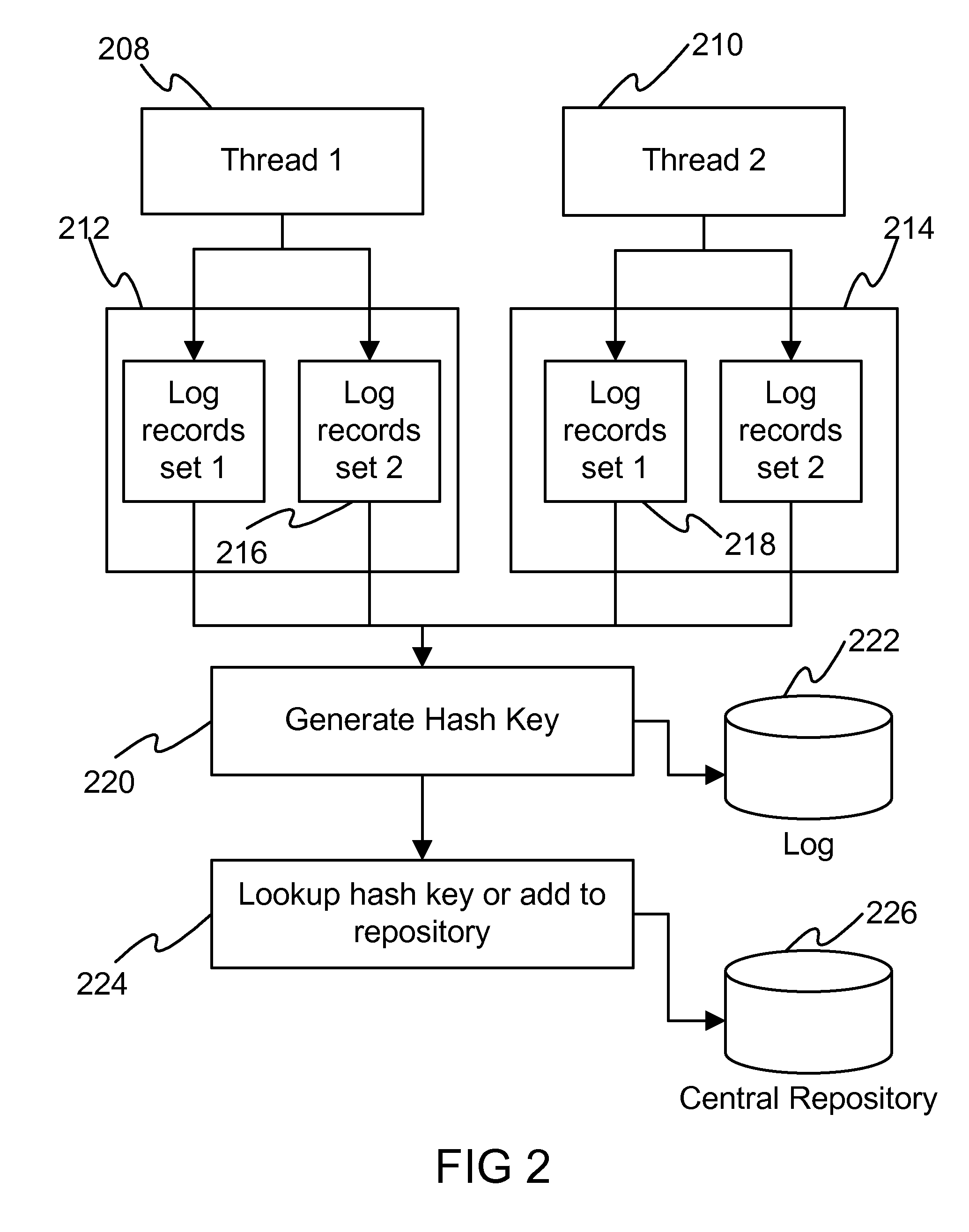
[0004]An embodiment of this invention provides the following steps: to create a hash key from a set of log records that are supposed to be written to the log file (and to write only the hash key, instead of the set of log records). The hash key takes a very small field and takes little storage space, compared to the set of log records, thus, greatly reducing the size of the log files. The set of log records are stored in a centralized repository of log records and are looked up during the analysis of the log information, using the hash key. This could be done through the development of a simple tool. The centralized repository of log records can be prepared at various stages of development lifecycle, like development, testing, etc (and even during support and maintenance).
[0009]3) Centralized repository for log keys—enhances reuse of log lines and helps in tagging log sections.
[0010]4) Reduced I / O operation—log records are grouped and written once to the file, which reduces the I / O operations involved. Thus, it enables tracing for applications.

Problems solved by technology

The log files grow to huge sizes over time and severely hamper the effective usage of them.
People and applications that use the log files, for analysis of the activity carried out by the system, find it difficult to search for the necessary sections in the logs due to the sheer size of the logs.
These applications, however, do not reduce the amount of data that is recorded in the log files, and also, their performance deteriorates with the increase in the size of log files.

Method used


Image

  • Reducing log entries using hash keys
  • Reducing log entries using hash keys
  • Reducing log entries using hash keys

Examples


Embodiment Construction

[0013]In an embodiment of the invention, log records are written during the execution of the programs. Developers generally make use of standard logging method in their applications. The simplest example of writing a log record is by calling the log() or trace() method on a Java or C++ class after the initialization of the class. Calling the log() method writes the corresponding parameter passed to the log file. The disclosure described in this document proposes the log records to be held in a vector, forming a set of log records that identify a particular execution flow in a program. This is explained with the help of an example, as shown below:

[0014]The typical way of writing flow of program execution as log records is as follows, e.g.:[0015]1>[0016]log(“line 1 to log”);[0017]2>[0018]log(“line 2 to log”);[0019]if then[0020]3>[0021]log(“line 3 to log”);[0022]log(“line 4 to log”);[0023]else[0024]4>[0025]log(“line 5 to log”);[0026]end if[0027]log(“line 6 to log”);

[0028]In an embodim...


PUM


Abstract

An example of this presentation deals with the way the events emitted from a component can be grouped from the development phase, so that when the problem occurs in the production environment, the problem could be tracked easily and analyzed. The embodiment deals with the program having multiple separate paths for execution. The execution path could be the normal flow of events grouped together (and generating a key to represent the normal flow). The other execution paths could represent the alternate flows, also grouped, and a key is generated to represent which one is deviated from normal flow. The database stores the key and the relative event flow information, which indicates the grouped events. The lookup viewer can be provided for viewing the normal and alternate flows, since the event has been logged as keys. A “Key” is a hash on the static content of the events, which is used to identify a particular start and end of the functionality in a flow of execution.

Description

BACKGROUND OF THE INVENTION[0001]Virtually, every system in the IT infrastructure exposes the activity being carried out by it, using logging. Log files are the primary source of finding out the various aspects of a system. A developer checks the log files to see if the program he or she developed is running as expected. The various flows of execution of a program are inspected by the log records written to the log file by the program. An administrator of a system checks the log files to see the reasons an application is failing to execute as required. Log files provide the administrator with the first-step-information on what is going wrong with the application. Numerous examples could be stated mentioning the scenarios where log files help developers, administrators, or even customers, under various circumstances, such as problem determination.[0002]The log files grow to huge sizes over time and severely hamper the effective usage of them. People and applications that use the log ...

Claims


Application Information

Patent Timeline
IPC IPC(8): G06F11/00G06F11/30
CPCG06F11/3688
Inventor CHILUKURI, SAMPATH KUMARDORAISAMY, KALPANA
Owner IBM CORP
Learn More