Marine fuel vapor separator with vent control device

a technology of vent control device and fuel vapor separator, which is applied in the direction of liquid fuel feeder, machine/engine, combustion air/fuel-air treatment, etc., can solve the problems of fuel vapor, fuel readily vaporizing, and threat of vapor lock

Active Publication Date: 2009-03-17
CARTER FUEL SYST
View PDF20 Cites 24 Cited by
  • Summary
  • Abstract
  • Description
  • Claims
  • Application Information

AI Technical Summary

Benefits of technology

[0012]The invention comprises a fuel supply system for an outboard marine engine. The fuel supply system includes a vapor separator having an enclosed interior chamber for collecting a volume of liquid fuel and fuel vapors. A suction pump transfers the liquid fuel under negative pressure from a remote fuel tank to the interior chamber of the vapor separator. A high pressure pump transfers liquid fuel under positive pressure from the interior chamber to a fuel injection system of the engine. The vapor separator includes a vent valve device communicating with the interior chamber for permitting the escape of fuel vapors trapped in the interior chamber. The vent valve device includes a generally tubular casing having an enclosed top end permeated by an escape passage. A float is slidably disposed within the casing for movement toward and away from pressing engagement with the escape passage. A sealing feature perfects a fluid and vapor tight seal between the float and the escape passage when the float is pressed thereagainst. The vent valve device further includes a biasing element operatively interposed between the casing and the float for urging the float toward the escape passage.
[0013]A fuel supply system according to the subject invention overcomes the shortcomings and disadvantages of the prior art by providing a uni-directional vent valve device for the vapor separator of an outboard marine engine. Thus, the uni-directional nature of the vent valve device prevents liquid fuel leakage from the engine when it is tipped in any direction. Therefore, if the outboard marine engine is laid on its side for transportation, fuel will not leak.
[0014]The invention also contemplates a vapor separator including a uni-directional vapor vent device for a fuel supply system for an outboard marine engine. The vapor separator includes an enclosed interior chamber for collecting a volume of liquid fuel and fuel vapors. A top wall encloses the interior chamber and includes a vapor outlet. The vent valve device is disposed in the top wall and communicates with the vapor outlet for permitting the escape of fuel vapors trapped in the interior chamber through the vapor outlet. The vent valve device includes a generally tubular casing having an enclosed top end permeated by an escape passage. A float is slidably disposed within the casing for movement toward and away from pressing engagement with the escape passage. A sealing feature perfects a fluid and vapor tight seal between the float and the escape passage when the float is pressing thereagainst. The vent valve device includes a biasing element operatively interposed between the casing and the float for urging the float toward the escape passage.

Problems solved by technology

Fuel vapor is a long recognized issue in the marine fuel industry.
However, at such low pressures, the fuel readily vaporizes.
This, combined with the high temperatures and jarring conditions, leads to a threat of vapor lock.
If the outboard marine engine is laid on its side, which would be the intuitive method so as to protect the prop and tiller arm, the pivotal axis of the vent valve mechanism is not likely to permit closure of the float valve.
As a consequence, it is possible for liquid fuel to leak from the engine into the vehicle.

Method used


Image

  • Marine fuel vapor separator with vent control device
  • Marine fuel vapor separator with vent control device
  • Marine fuel vapor separator with vent control device

Examples


Embodiment Construction

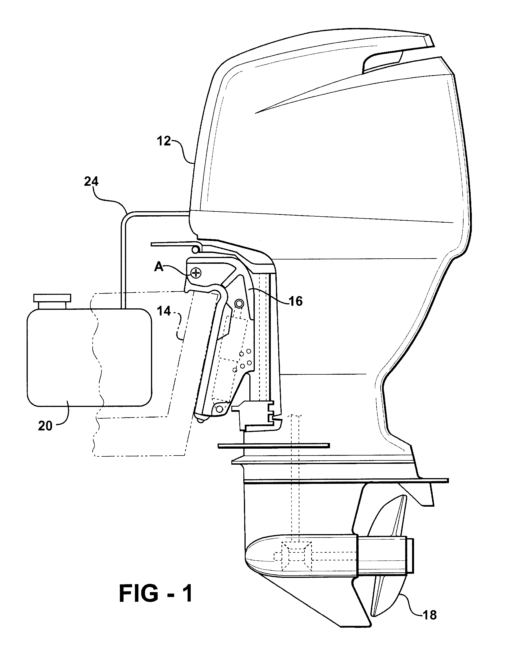
[0028]Referring to the Figures, wherein like numerals indicate like or corresponding parts throughout the several views, a general depiction of an outboard marine engine 12 affixed to the transom 14 of a boat is shown in FIG. 1. Small outboard marine engines 12 of this type are usually mounted on a bracket 16 so that the engine 12 can be quickly removed from the boat for transportation and / or maintenance. The bracket 16 includes a tilting feature which allows the motor head to be rotated into the boat, with the propeller 18 swinging up out of the water, to facilitate launching and maneuvering through shallow conditions. As an example, the motor 12 may be pivoted about axis A between these use and non-use positions, as well as for trim control.

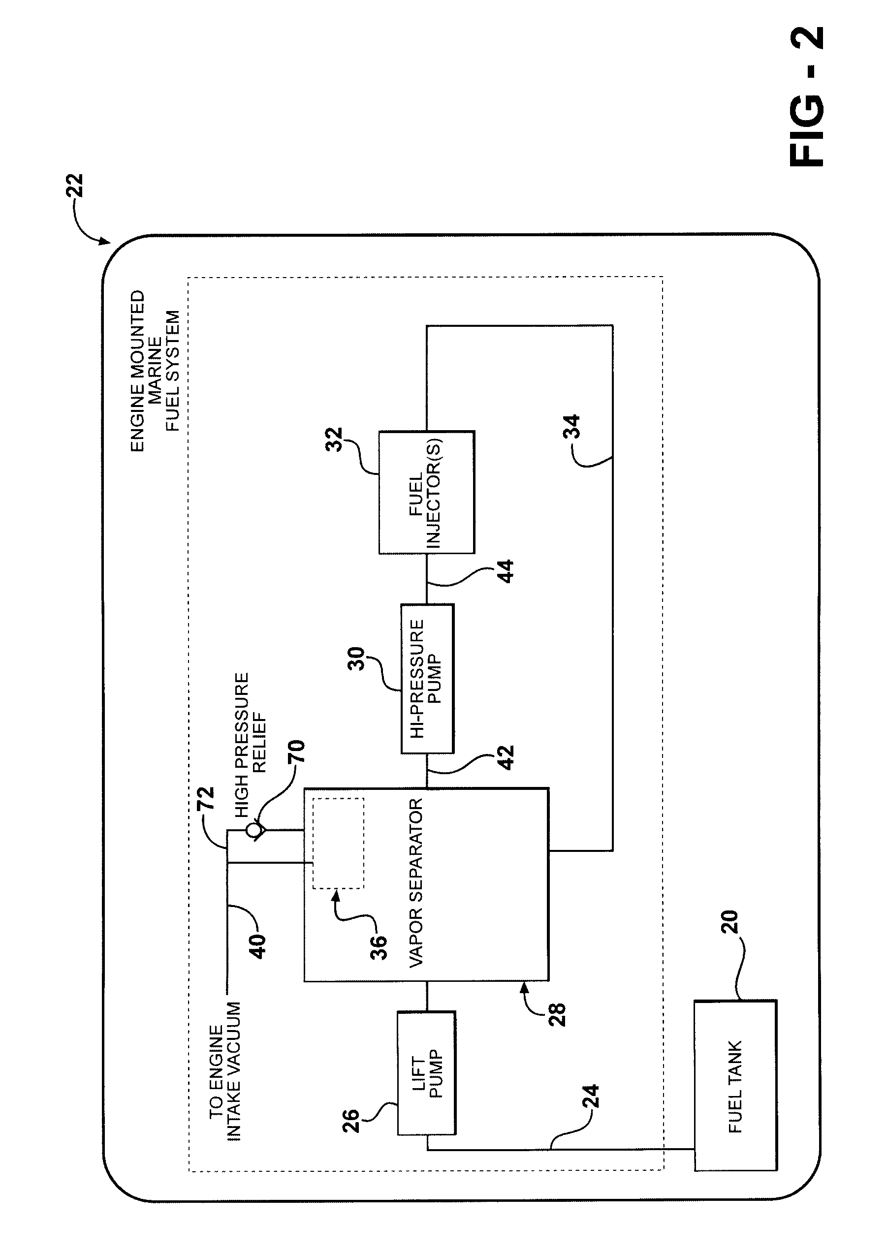
[0029]An engine of the type shown in FIG. 1 commonly runs on a liquid fuel like gasoline or ethanol. Liquid fuel is drawn from a fuel tank 20 by an engine-mounted marine fuel system, generally shown at 22 in FIG. 2. Except for the fuel tank 20 ...


PUM


Abstract

A fuel supply system for an outboard marine engine includes a vapor separator (28) having a uni-directional vapor vent device (36) for preventing fuel leakage when the engine (12) is tipped on its side. The vapor separator (28) includes an enclosed interior chamber (50) which is filled with liquid fuel by a suction pump. A separate, high pressure pump transfers the liquid fuel from the interior chamber (50) to a fuel injection system (32) of the engine (12). The vapor vent device (36) includes a generally tubular casing having an enclosed top end permeated by an escape passage (84), and a float (94) slidably disposed within the casing (82) for movement toward and away from sealing engagement with the escape passage (84). A spring (98) urges the float (94) toward a sealed condition against the escape passage (84), but is too weak to overcome the weight of the float (94) unless the engine (12) is tipped more than about 25 degrees from vertical, or unless the level of fuel in the interior chamber (50) lifts the float (94).

Description

CROSS REFERENCE TO RELATED APPLICATIONS[0001]This application claims priority to U.S. provisional application entitled Marine Fuel Vapor Separator with Vent Control Device having Ser. No. 60 / 727,151 and filed Oct. 14, 2005.BACKGROUND OF THE INVENTION[0002]1. Field of the Invention[0003]The present invention relates to a fuel vapor separator used in a fuel delivery system of a marine engine for preventing fuel spills when the engine is tipped sideways.[0004]2. Related Art[0005]Small outboard marine engines are usually detachably mounted to the transom of a boat. These engines typically include an integrated fuel system which draws liquid fuel under suction from a can or tank in the boat. The fuel is routed through a vapor separator unit to condense or discharge vapors and then delivered at high pressure to a fuel injection system.[0006]Fuel vapor is a long recognized issue in the marine fuel industry. The fact that fuel is withdrawn from the tank at negative pressure is a main factor...

Claims


Application Information

Patent Timeline
Patent Type & Authority Patents(United States)
IPC IPC(8): F02M37/04F16K24/00
CPCF02M37/20Y10T137/86324F02M25/08F02M37/14F02M37/04
Inventor ACHOR, KYLE D.
Owner CARTER FUEL SYST
Why Eureka
Try Eureka