Mechanical rotational drive

a rotational drive and rotating shaft technology, applied in the direction of motors, cosmonautic parts, cosmonautic components, etc., can solve the problems of increasing weight, heavy and therefore expensive, and complex design of conventional mechanical systems, and achieves low weight, low degree of complexity, and small bearing clearance

Inactive Publication Date: 2009-03-17
EADS SPACE TRANSPORTATION
View PDF20 Cites 5 Cited by
  • Summary
  • Abstract
  • Description
  • Claims
  • Application Information

AI Technical Summary

Benefits of technology

[0011]The invention is directed to a mechanical rotational drive that has a small bearing clearance with a low weight and low degree of complexity and thus can achieve a high positioning accuracy and can be produced in a cost-effective manner with high degree of reliability.
[0014]The provision according to the invention of a damping device in the axial direction of the torsion element at a fixed distance from the bearing device and adjacent to the free end of the torsion element and the provision of the damping part in the area of the free end of the torsion element such that the damping part in the relaxed position of the torsion element is in friction engagement with the damping device and in the relaxed position of the torsion element is not engaged with the damping device, utilizes in a skillful, novel manner the effect that the torsion element is slightly lengthened in the relaxation in the axial direction so that with this lengthening of the torsion element the damping device and the damping part can become engaged with one another. The torsional movement of the torsion element from its tensioned position into the relaxed position is thus slowed down at the end or shortly before the end of the torsional path provided by the friction engagement between the damping part and the damping device so that it can reach its precise predetermined target position. This friction engagement also prevents the torsion element, while slowing down, from performing a torsional vibration around the target position, since the friction engagement damps a vibration of this type at the very start.
[0015]It is particularly advantageous if the torsion element has a central support bar that suppresses a bending of the torsion element along its longitudinal axis and thus increases the static stability of the torsion element.
[0016]It is also advantageous if the torsion element has elastic flexural bars arranged in an annular manner parallel to the longitudinal axis, which bars are clamped in an annular manner in the bearing device and in the device for transmitting a torque. This annular arrangement of flexural bars makes it possible to create a particularly light torsion element that, with a compact design, renders possible large torsion angles and an effective clear change of length over the torsional path. It is thereby particularly advantageous if the flexural bars comprise a carbon fiber material, which further reduces the weight.
[0019]A particularly advantageous embodiment of the mechanical rotational drive according to the invention is wherein the damping part has at least one friction surface that is rotatable around the rotation axis and that the damping device has at least one friction surface that is arranged at least in sections around the rotation axis. This concentric arrangement of damping part and damping device around the rotation axis makes it possible to build up the damping force slowly and continuously over a predetermined distance of a path of the rotational movement and thus obtain a particularly effective damping and slowing down of the torsion element, since the change of length of the torsion element increases the frictional force between damping part and damping device.
[0021]It is even more effective if the friction surfaces are embodied as conical surfaces around the rotation axis, whereby they can be embodied in a tapered conical or spherically conical manner.

Problems solved by technology

In order to achieve this aim, conventional mechanical systems are complex in design, heavy and therefore expensive.
A serious problem with conventional mechanical systems is the bearing clearance that as a rule does not guarantee an exact positioning of an external structure to be extended.
To this end separate mechanical means, such as, e.g., engagement devices, are frequently necessary, the provision of which, however, in turn increases the weight and thus the expense and also the complexity of the overall arrangement, which regularly has a negative impact on the reliability of the overall system.

Method used


Image

  • Mechanical rotational drive
  • Mechanical rotational drive
  • Mechanical rotational drive

Examples


Embodiment Construction

[0030]The particulars shown herein are by way of example and for purposes of illustrative discussion of the embodiments of the present invention only and are presented in the cause of providing what is believed to be the most useful and readily understood description of the principles and conceptual aspects of the present invention. In this regard, no attempt is made to show structural details of the present invention in more detail than is necessary for the fundamental understanding of the present invention, the description taken with the drawings making apparent to those skilled in the art how the several forms of the present invention may be embodied in practice.

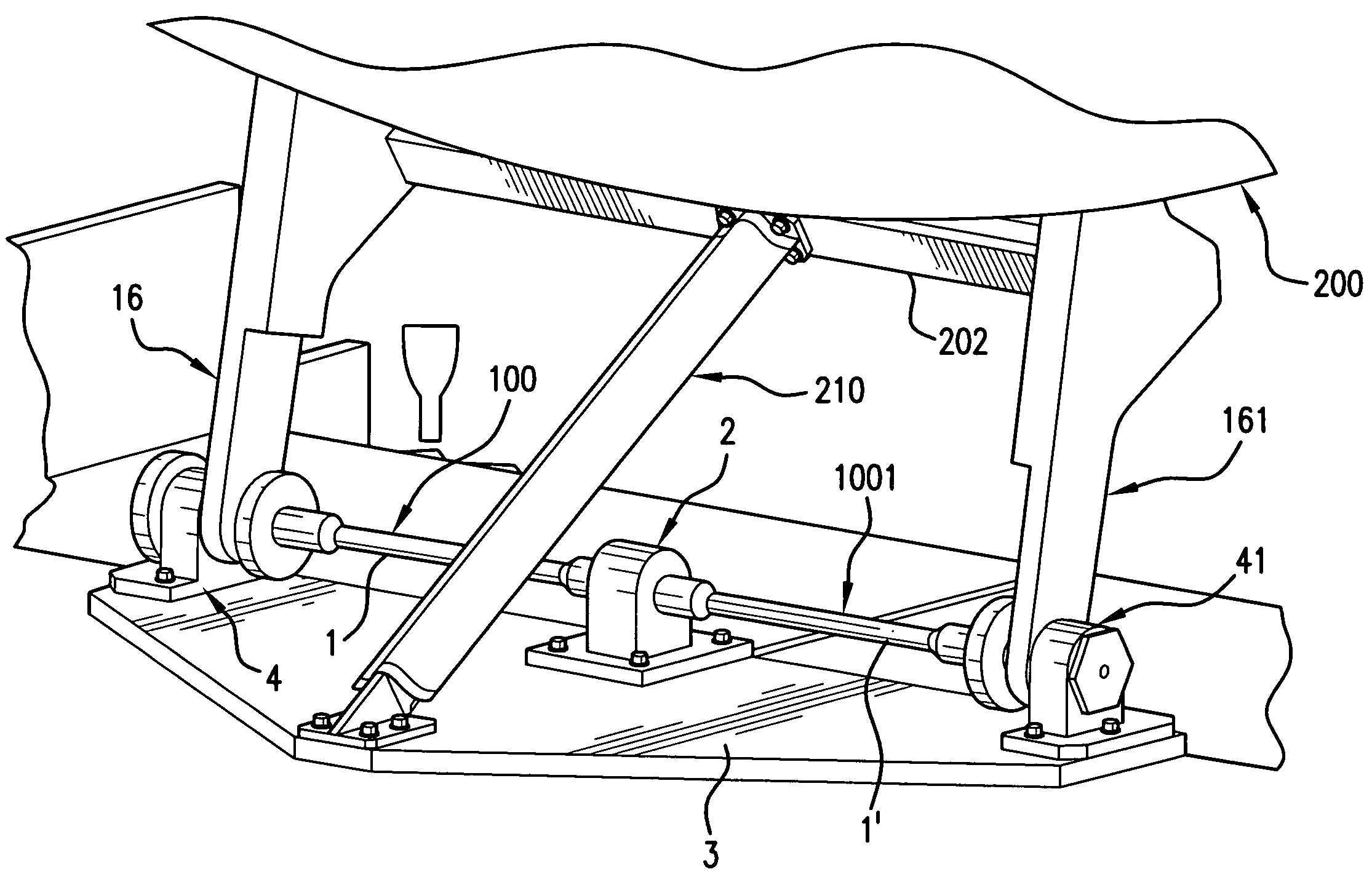
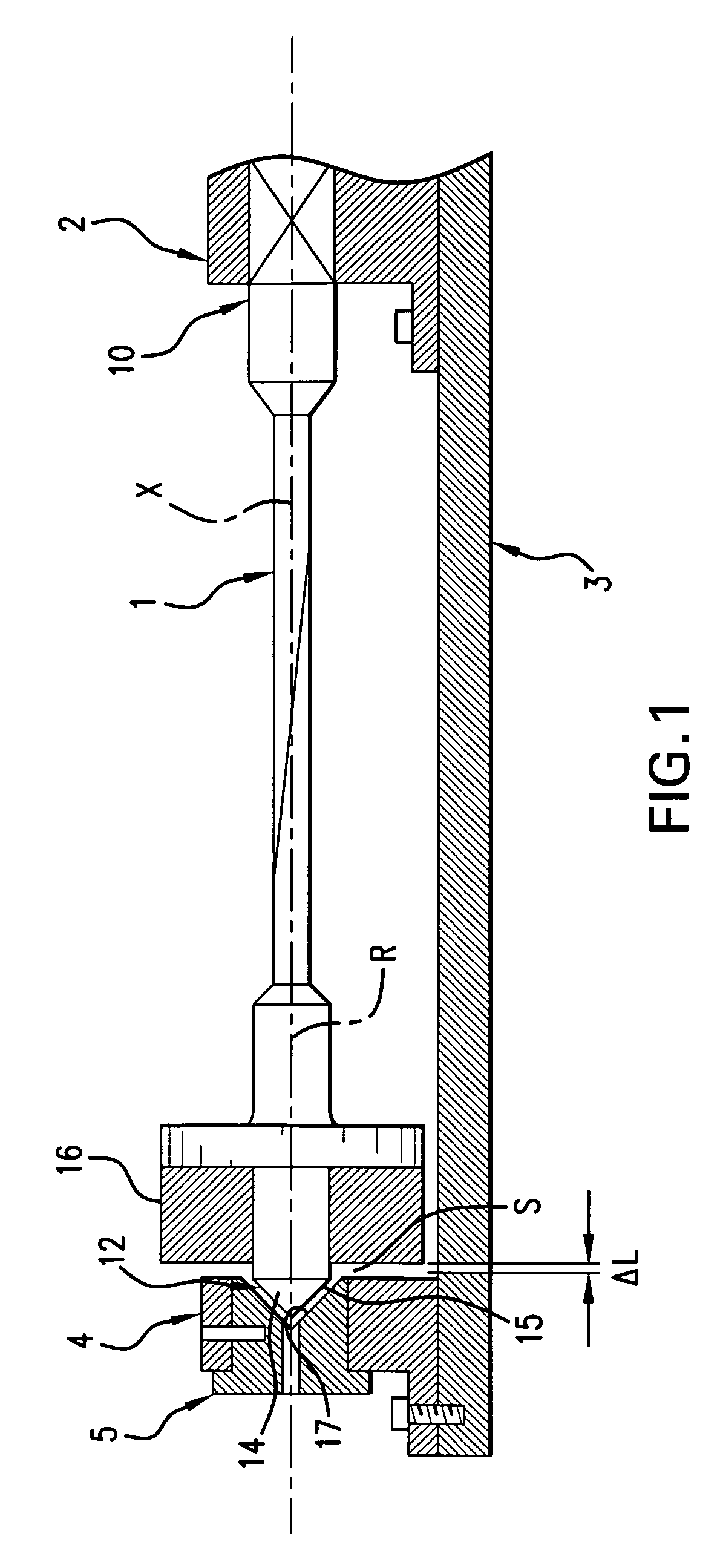
[0031]FIG. 1 shows in diagrammatic form a mechanical rotational drive according to the invention. A bar-like torsion element 1 is firmly clamped with a first end 10 in a bearing device 2. The bearing device 2 is firmly attached to a base 3. The base 3 can be, e.g., an outer structural element of a spacecraft, on which an ...


PUM


Abstract

A mechanical rotational drive has a bar-like torsion element, whereby the torsion element is firmly clamped with a first end in a bearing device. The torsion element can be pivoted with a second free end with respect to the clamped end about the longitudinal axis, forming a rotation axis, of the torsion element between a relaxed position and a tensioned position, whereby the length of the torsion element is reduced with respect to the relaxed position when the torsion element is brought into its tensioned position. A device for transmitting a torque into the torsion element or out of the torsion element is provided in the area of the free end, and a damping device is arranged in the axial direction of the torsion element at a fixed distance from the bearing device and adjacent to the free end of the torsion element, and a damping part is provided on the torsion element in the area of the free end of the torsion element, which damping part in the relaxed position is in friction engagement with the damping device and which in the tensioned position is not engaged with the damping device.

Description

CROSS-REFERENCE TO RELATED APPLICATION[0001]This application claims priority under 35 U.S.C. §119 of German Patent Application No. 10 2005 021 459.2, filed on May 10, 2005, the disclosure of which is hereby incorporated by reference thereto in its entirety.BACKGROUND OF THE INVENTION[0002]1. Field of the Invention[0003]The present invention relates to a mechanical rotational drive with a bar-like torsion element.[0004]2. Discussion of Background Information[0005]A variety of mechanical rotational drives are known. In particular, such drives are used in space engineering in order, e.g., to effect one-time actuations of external structures on satellites, e.g., the extension of antennas or solar panels. Such rotational drives have the advantage that they can be preloaded with a mechanical energy on earth before the start of a space mission, which energy is then emitted in space to perform the desired actuation. This actuation is therefore not dependent on the very limited electric ener...

Claims


Application Information

Patent Timeline
Patent Type & Authority Patents(United States)
IPC IPC(8): F03G1/00
CPCB64G1/222F16F1/16F16F15/063
Inventor SPERBER, FRANZSTICH, WALTERSTIELNER, LEONHARDWAGNER, ADALBERT
Owner EADS SPACE TRANSPORTATION
Why Eureka
Try Eureka