Winch device

a technology of winch device and winch shaft, which is applied in the direction of winding mechanism, hoisting equipment, etc., can solve the problems of unnecessary and complicated hydraulic or electrical control devices, and achieve the effects of good symmetrical force distribution, reliable transverse force compensation, and compact arrangemen

Inactive Publication Date: 2009-03-17
BAUER MASCH GMBH
View PDF21 Cites 8 Cited by
  • Summary
  • Abstract
  • Description
  • Claims
  • Application Information

AI Technical Summary

Benefits of technology

[0018]According to the invention a particularly compact arrangement with a good symmetrical force distribution is achieved in that the driving shafts and winch drums are oriented parallel to the differential shaft and that the latter is positioned centrally between the two winch drums. A mirror symmetrical arrangement of the two winches to a centre plane through the differential shaft ensures a reliable compensation of transverse forces on said differential shaft. This is also advantageous for a simple and compact construction.
[0019]According to another preferred embodiment of the inventive winch device, for driving the differential shaft is provided a first extension shaft, which is connected in rotary manner to the first driving shaft, together with a second extension shaft, which is connected to rotate with the second driving shaft, and that the first extension shaft and second extension shaft project from a housing for bearing the winch drums. Through the use of an extension shaft attached in detachable manner to the driving shaft, a conventional winch can be easily adapted for the invention. The extension shafts project out of a bearing housing of the winch drums, so that a rotary connection with the differential shaft can easily be constructed on the outside of the housing.
[0020]According to the invention, a cost and manufacturing advantage results from the first and second winches having an identical construction.

Problems solved by technology

Here, complicated hydraulic or electrical control devices become unnecessary.

Method used


Image

  • Winch device
  • Winch device
  • Winch device

Examples


Embodiment Construction

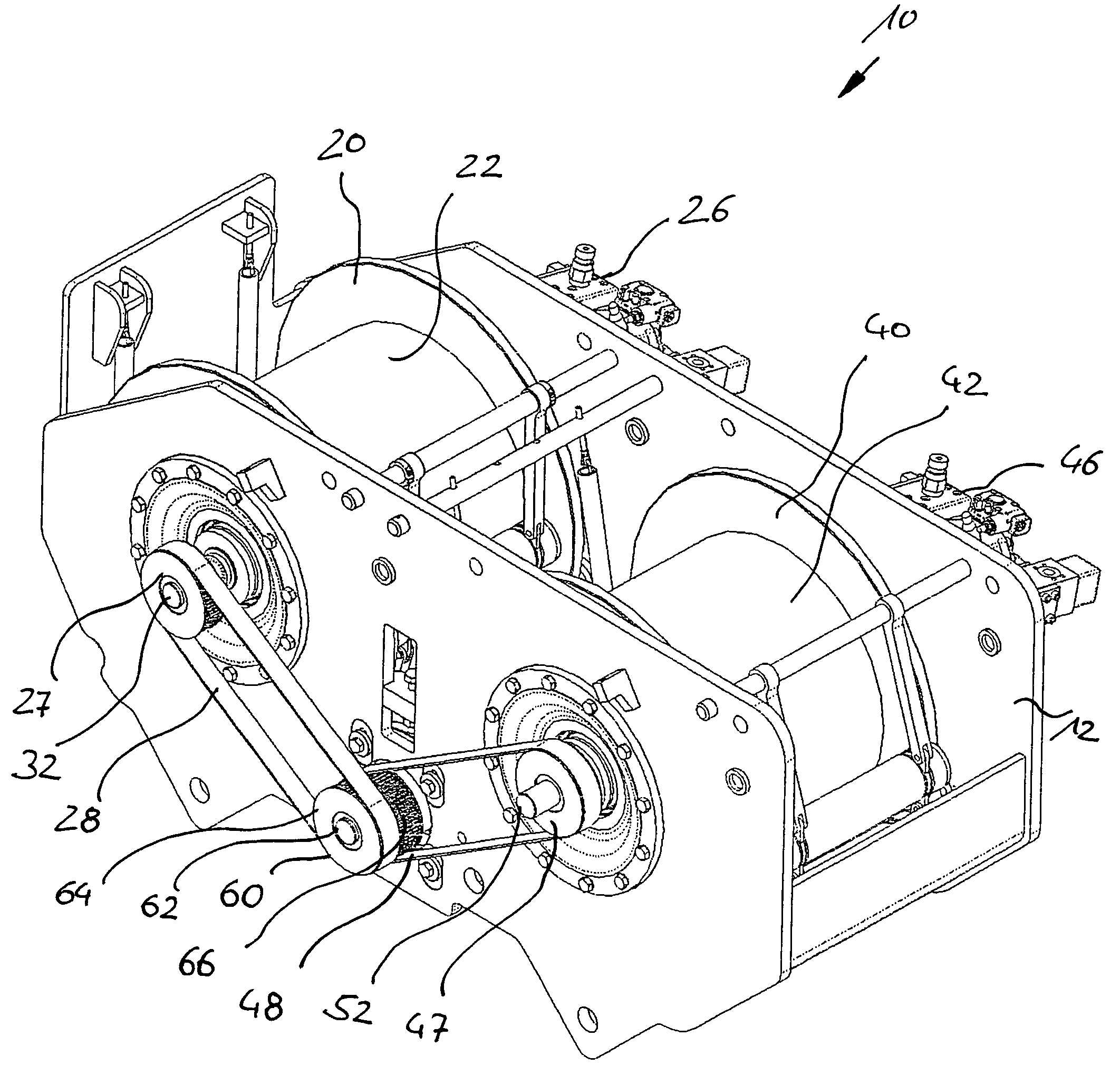
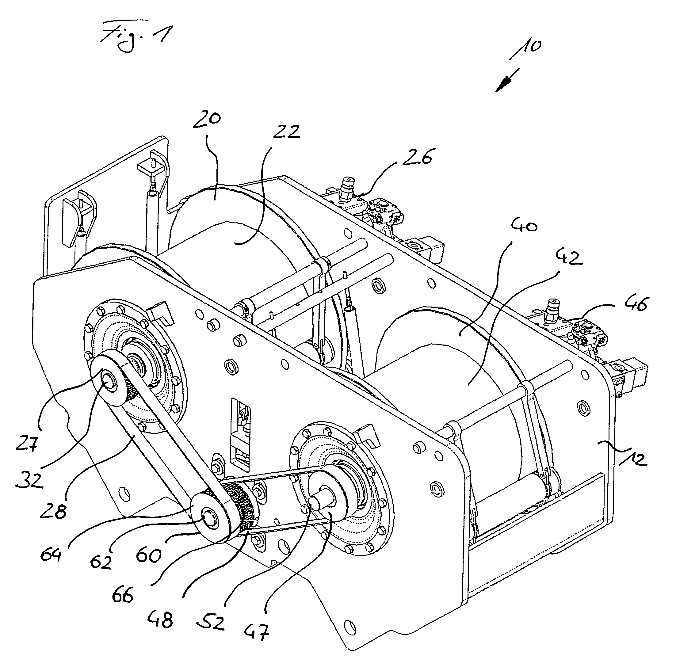
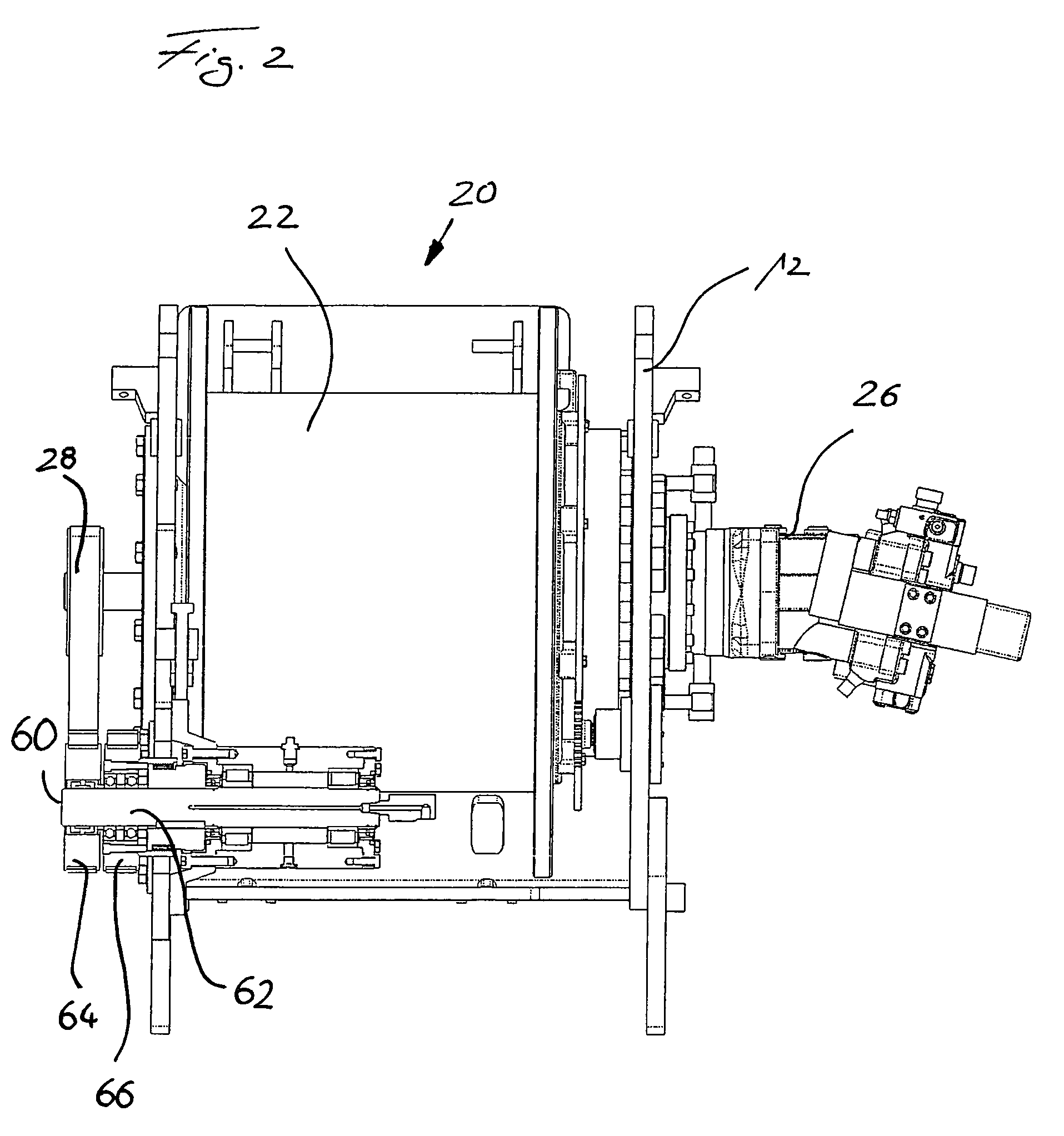
[0026]According to FIGS. 1 and 2 an inventive winch device 10 has a box-type, top open housing 12, in which are positioned in parallel, juxtaposed manner a first winch 20 and a second winch 40. A first winch drum 22 and a second winch drum 42 are pivotably mounted in housing 12. A synchronizing device 60 with a differential shaft 62 is positioned centrally between the two winches 20, 40. A first synchronous wheel 64 and a second synchronous wheel 66 are located on differential shaft 62, which projects from one side of housing 12.

[0027]The first synchronous wheel 64, which is connected to rotate with differential shaft 62, is in rotary connection with a first driving wheel 27 by means of a band-shaped, toothed driving belt 28. Said first driving wheel 27 is connected to rotate on an extension shaft 32 driven by means of a first, hydraulic drive 26 of the first winch 20. In the same way a second extension shaft 52 of the second winch 40 is driven by a second, hydraulic drive 46 of the...


PUM


Abstract

The invention relates to a winch device with a first winch having a first winch drum and a second winch having a second winch drum. There is also a synchronizing device through which a rotation of the first winch drum can be synchronized with the rotation of the second winch drum. Further, a differential shaft with a first synchronous wheel and a second synchronous wheel is provided, said first synchronous wheel being connected via a first rotary connection device to a first drive and the second synchronous wheel is connected via a second rotary connection device to the second drive.

Description

BACKGROUND OF THE INVENTION[0001]1. Field of the Invention[0002]The invention relates to a winch mechanism having a first winch with a first winch drum driven in rotary manner by a first drive via a first gear, a second winch with a second winch drum driven in rotary manner by a second drive via a second gear, and a synchronizing device making it possible to synchronous a rotation of the first winch drum with a rotation of the second winch drum.[0003]2. Related Art[0004]Such double winch mechanisms with two winch drums and two separate drives are more particularly used for cranes and other lifting devices. A force distribution over at least two cables is advantageous for strength and safety reasons. Production and cost advantages result from the use of two smaller drives in place of one large drive. The use of two winch drums basically permits a joint and a separate operation of the cables, so that high functionality results from such a winch mechanism.[0005]Such a winch mechanism c...

Claims


Application Information

Patent Timeline
Patent Type & Authority Patents(United States)
IPC IPC(8): B66D1/14
CPCB66D1/16B66D1/26B66D1/02B66D1/08B66D1/20
Inventor ARZBERGER, MAXIMILIANOSTERMAIER, CHRISTIAN JOHANNESHUBER, LUDWIG ANDREASSEITLE, IGNAZ
Owner BAUER MASCH GMBH
Why Eureka
Try Eureka