Boiler feed water deaerator method and apparatus

a degasification method and boiler technology, applied in lighting and heating equipment, liquid degasification, separation processes, etc., can solve the problems of significant corrosion in the steam system, steam line, steam condenser, condenser, etc., and achieve the effect of reducing the oxygen containing water supply stream

Active Publication Date: 2009-03-17
WESTLAKE CHEM CORP
View PDF36 Cites 2 Cited by
  • Summary
  • Abstract
  • Description
  • Claims
  • Application Information

AI Technical Summary

Benefits of technology

[0009]A nitrogen sweep stream is then supplied to the deaerator water tank during deaerator operations. The nitrogen sweep stream thereby diffuses any remaining oxygen in the water supply stream resulting in a substantial portion of the remaining oxygen being removed from the water supply stream to produce a reduced oxygen containing water supply stream. The nitrogen sweep stream also substantially removes any remaining carbon dioxide contained within the water supply stream. The reduced oxygen containing water supply stream is then supplied to a boiler as a feed water stream having substantially reduced oxygen and carbon dioxide contained therein. The nitrogen sweep stream is maintained during deaerator operations to remove oxygen and carbon dioxide from the water supply stream.

Problems solved by technology

Oxygen and carbon dioxide contained within boiler feed water cause significant corrosion in the steam system, namely the boiler tubes, steam lines, condensate lines, and heat transfer equipment.
Additionally, if the boiler feed water has oxygen in it, the oxygen may cause corrosion to surface condensers which may release copper.
The released copper in the steam system may create a major problem when it is necessary to make any repair welds to the steam system.
Although deaerators are able to remove a large portion of the oxygen and carbon dioxide, many times the stripping capabilities of the deaerator are inadequate to remove enough oxygen and carbon dioxide to sufficiently minimize corrosion within the steam system.
Oxygen scavengers are very expensive and add considerable operating costs to the steam system.

Method used


Image

  • Boiler feed water deaerator method and apparatus
  • Boiler feed water deaerator method and apparatus

Examples


example 1

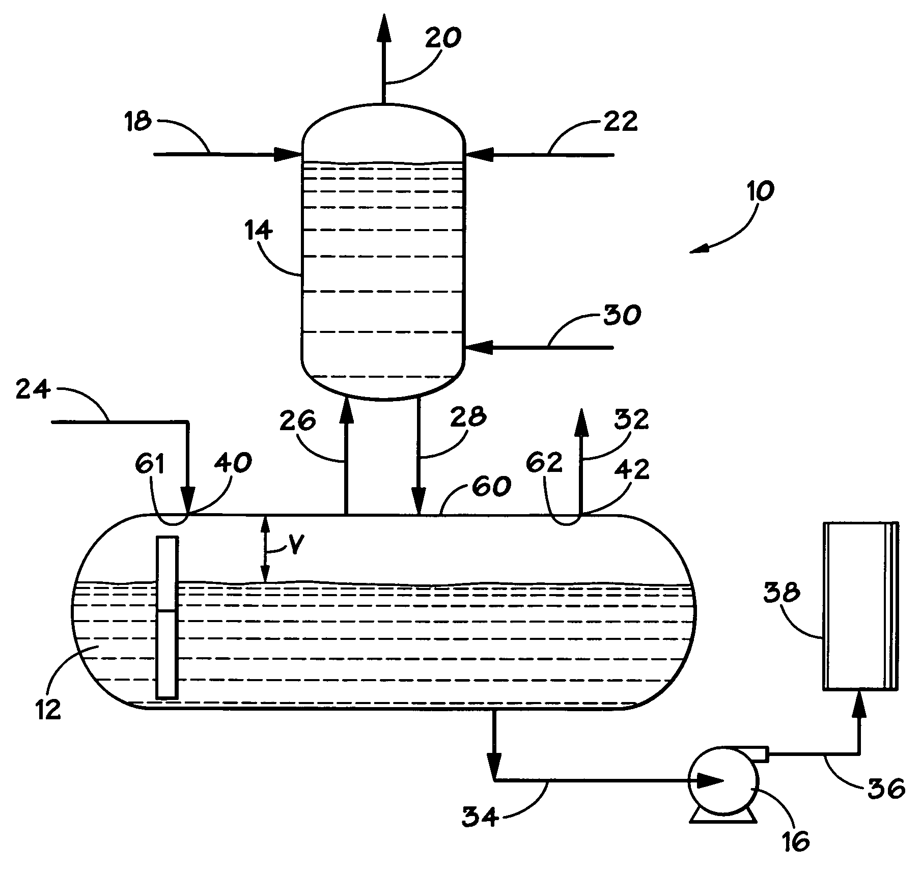
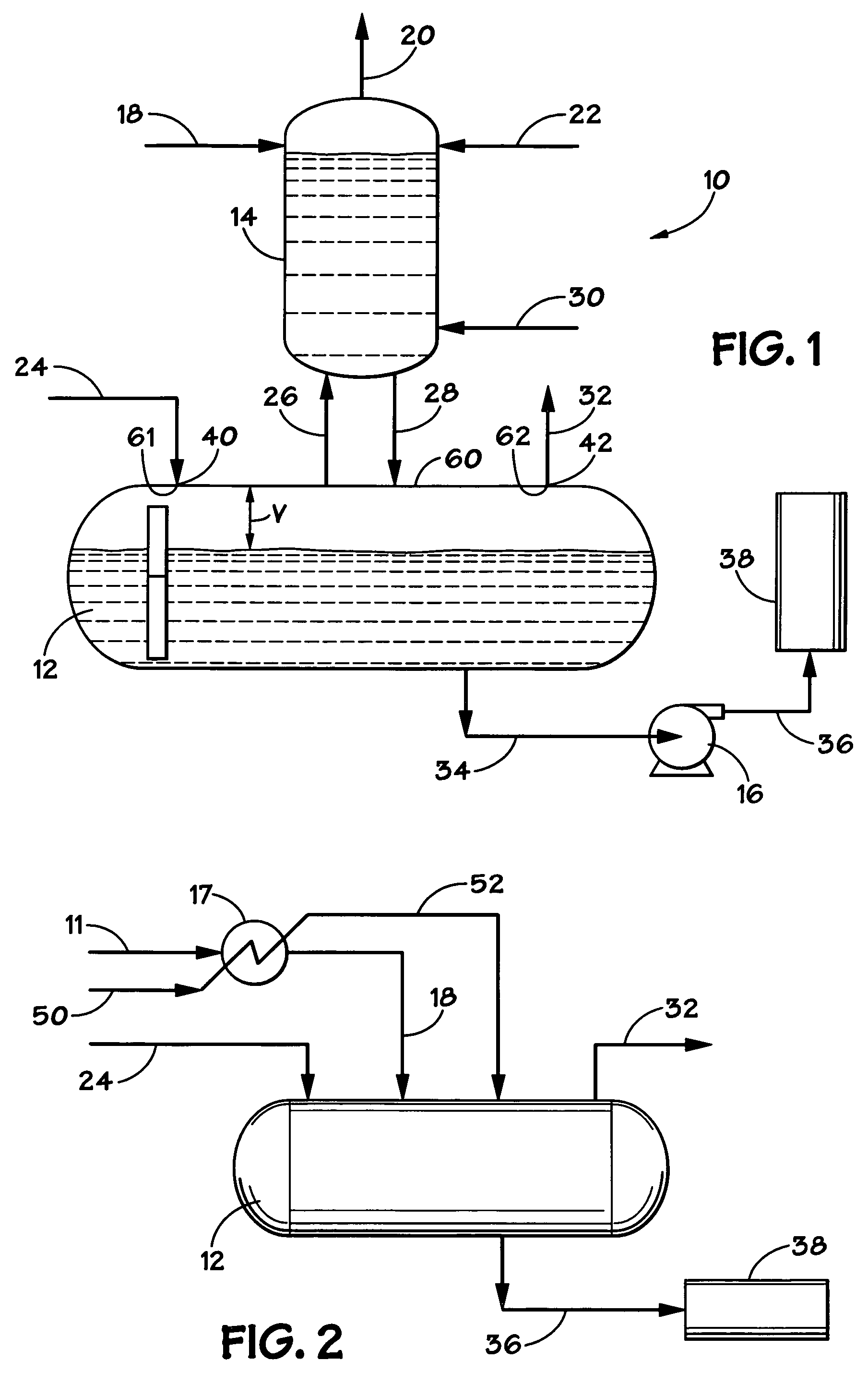
[0030]An ethylene production plant experienced a plant upset when its instrument air system failed. The ethylene plant utilized a deaerator to remove oxygen and carbon dioxide from its boiler feed water stream. In addition to the failure of the instrument air system, the incoming steam stream flow at the bottom of the deaerator stripper damaged the trays in the lower section of the deaerator stripper. Because the deaerator stripper trays had been damaged, the boiler feed water had an oxygen concentration well above the desired target of 7 ppb. Oxygen levels were detected as high as in the range of about 300 ppb to about 500 ppb as a result of the damaged trays preventing normal steam-water contact in its operation. Because repairing the trays would result in a costly, lengthy downtime, or offline, period, the plant operator decided to wait to repair the deaerator stripper trays. With such high levels of oxygen in the boiler feed water stream, corrosion was a serious concern if corre...


PUM

PropertyMeasurementUnit
pressureaaaaaaaaaa
temperatureaaaaaaaaaa
concentrationaaaaaaaaaa

Abstract

A nitrogen sweep stream for use in a deaerator during deaerator operations to disperse and remove oxygen and carbon dioxide from boiler feed water prior to being fed to a boiler. The nitrogen sweep stream substantially reduces the amount of oxygen and carbon dioxide in the water supply system. The water supply system can be sent to a deaerator stripper or can be heated using a heat exchanger. A heat water supply stream can also be sent directly to the deaerator water tank. The nitrogen sweep stream reduces the amount of oxygen contained with the boiler feed water stream to less than 7 ppb and reduces the amount of carbon dioxide to nondetectable levels. The nitrogen sweep may be provided to an existing deaerator, not having been previously provided with a nitrogen sweep, while the deaerator is running without shutting down the deaerator.

Description

RELATED APPLICATION[0001]This application claims the benefit and priority of U.S. Provisional Patent Application Ser. No. 60 / 633,918, filed Dec. 7, 2004.TECHNICAL FIELD[0002]The present invention relates to steam systems for petrochemical facilities. More specifically, the present invention relates to removal of oxygen from boiler feed water streams by utilizing a deaerator system.BACKGROUND OF THE INVENTION[0003]Deaerators are widely used in the petrochemical, refining, and power generation industries. A deaerator is a mechanical piece of equipment that is used to heat boiler feed water and to remove oxygen and carbon dioxide from boiler feed water, prior to the water being fed to the boiler. Oxygen and carbon dioxide contained within boiler feed water cause significant corrosion in the steam system, namely the boiler tubes, steam lines, condensate lines, and heat transfer equipment. Additionally, if the boiler feed water has oxygen in it, the oxygen may cause corrosion to surface ...

Claims


Application Information

Patent Timeline
Patent Type & Authority Patents(United States)
IPC IPC(8): B01D19/00
CPCB01D19/0005B01D19/0015C02F1/20F22D1/50C02F1/02C02F2103/02
Inventor ISTRE, KEN M.PAYNE, DAVID C.
Owner WESTLAKE CHEM CORP
Why Eureka
Try Eureka