Multi-function optical system and assembly

optical system technology, applied in the field of optical systems and optical systems, can solve the problems of complex and bulky prior art multi-function laser-based systems, and the need for an uncomplicated method of operating a multi-function optical system

Inactive Publication Date: 2009-03-17
RD2 LLC
View PDF15 Cites 34 Cited by
  • Summary
  • Abstract
  • Description
  • Claims
  • Application Information

AI Technical Summary

Benefits of technology

[0008]According to another aspect of the invention, the visible bore light (item (5) mentioned above

Problems solved by technology

Prior art multi-function laser-based systems are generally complex and bulky.
Additionally,

Method used


Image

  • Multi-function optical system and assembly
  • Multi-function optical system and assembly
  • Multi-function optical system and assembly

Examples


Embodiment Construction

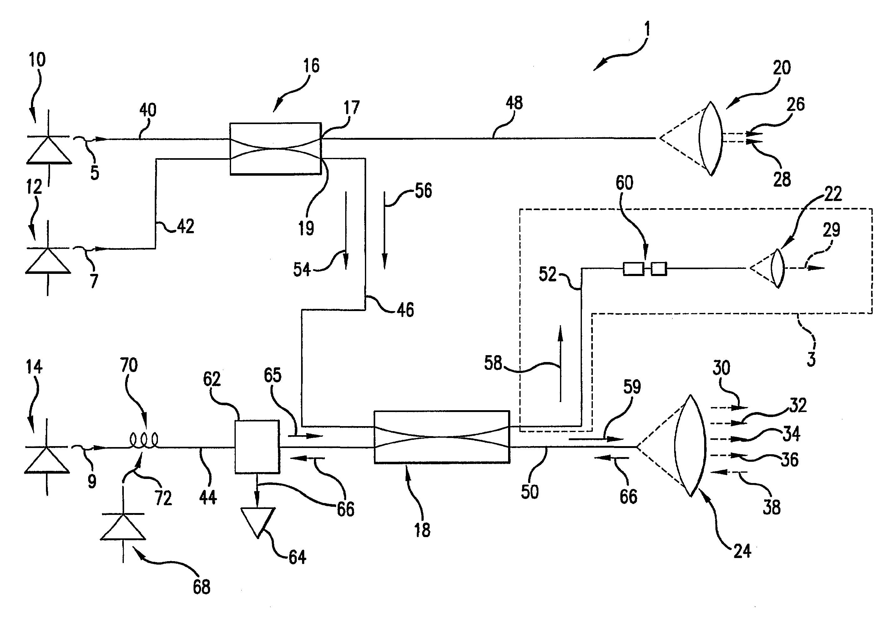
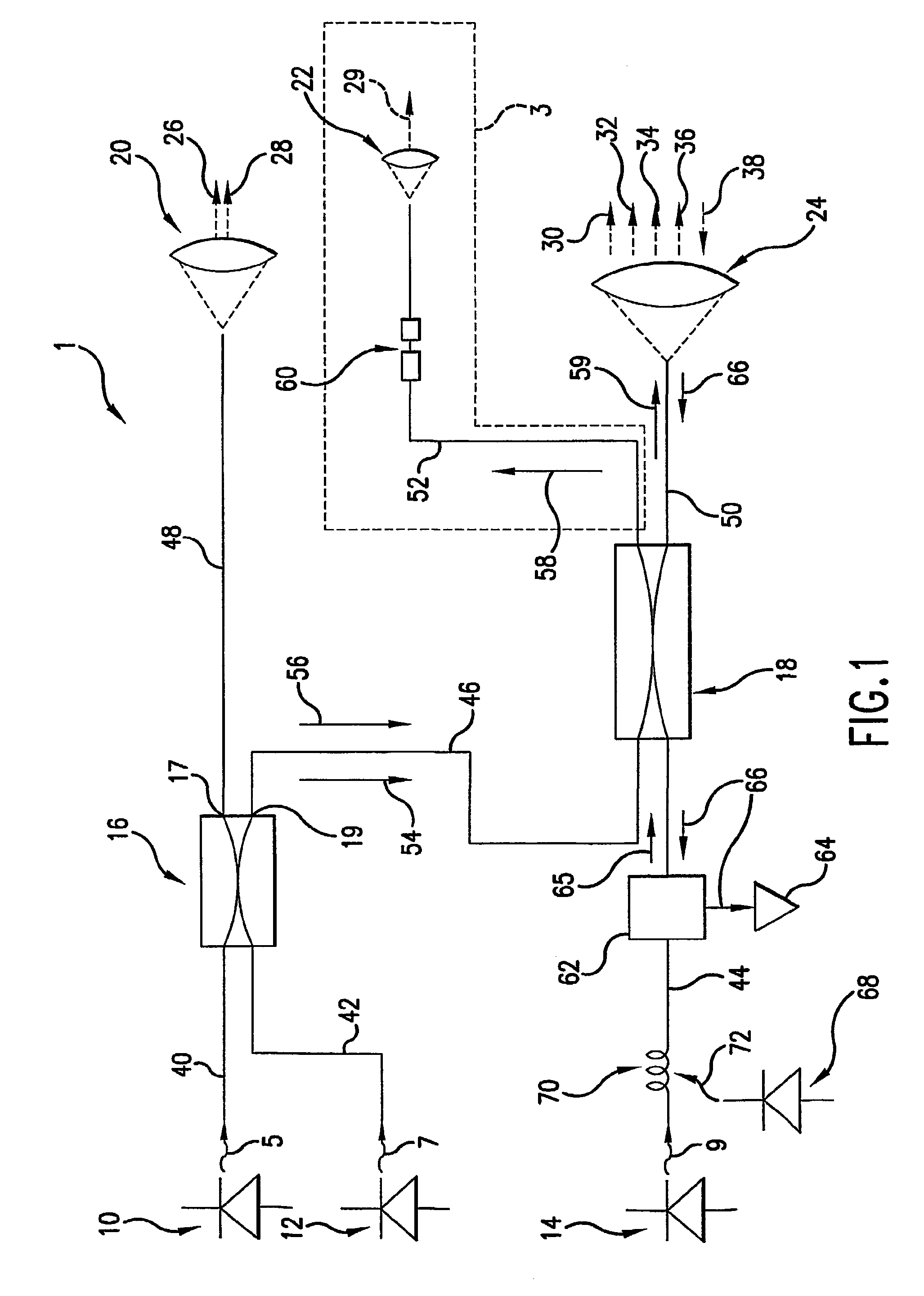
[0021]Referring now to the drawings, where like reference numerals designate like elements, there is shown in FIG. 1 an optical system 1 constructed in accordance with a preferred embodiment of the invention. The illustrated system 1 has a first source 10 for generating a first input laser energy 5. The first input energy 5 may have a wavelength in the near infrared spectrum (the infrared spectrum near the visible spectrum), for example from about 820 nanometers (nm) to about 860 nm, preferably about 825 nm.

[0022]The first input energy 5 propagates through an optical transmission line 40 and is launched into an optical coupler or splitter 16. The coupler 16 distributes optical power among two or more ports 17, 19. The coupler 16 directs a first portion of the input energy 5 into transmission line 48 and a second portion of the input energy 5 into transmission line 46 (in direction 56). The split of the first portion and the second portion will depend upon the requirements of the sys...


PUM


Abstract

An optical system or assembly is formed of a plurality of optical sources (10, 12, 14) and components of different laser-based equipment systems. The sources and/or components may be combined and/or eliminated to reduce complexity, cost and/or overall weight of the system by consolidating multiple laser sources into a reduced number of sources, and by multiplexing (19) different wavelength signals over common carriers. A laser engagement system (12, 14) and an infrared aim light (10) (or infrared illuminator) are powered by a single laser source which is adopted for use with conventional equipment by lengthening the duration of the coded pulses emitted by the transmitter. The transmitter may be triggered in response to the heat and/or pressure generated by the blank upon firing. A visible bore light may be eliminated by connecting infrared and/or visible aim light (10) directly to a rifle barrel. The laser engagement system and the infrared aim light (or infrared illuminator) are provided in a common housing assembly (410).

Description

FIELD OF THE INVENTION[0001]The present invention relates generally to optics and optical systems and devices. The present invention also relates to a method of operating a multi-function optical system. The present invention also relates to an assembly for a multi-function optical system.BACKGROUND OF THE INVENTION[0002]Multi-function laser-based systems are employed for a variety of purposes. For example, it has been suggested to provide up to seven different laser-based equipment systems in combination, including the following: (1) a laser range finder; (2) an infrared aim light; (3) an infrared illuminator (a flashlight); (4) a visible aim light; (5) a visible bore light (a mandrel boresight laser for aligning sights); (6) a combat identification system; and (7) a multiple integrated laser engagement system for laser-tag simulated exercises, referred to herein as a “laser simulation system.”[0003]Prior art multi-function laser-based systems are generally complex and bulky. There...

Claims


Application Information

Patent Timeline
IPC IPC(8): G01C3/06F41G3/26F41G3/14G01C3/08G01S7/481G01S17/87
CPCF41G3/145G01C3/08G01S7/4818G01S17/87
Inventor ROGERS, PHILIP L
Owner RD2 LLC
Why Eureka
Try Eureka