
Method for generating multivariate analysis model expression for processing apparatus, method for executing multivariate analysis of processing apparatus, control device of processing apparatus and control system for processing apparatus

a multi-variate analysis and model expression technology, applied in the direction of adaptive control, process and machine control, instruments, etc., can solve the problems of labor-intensive and time-consuming process of model expression generation and labor-intensive and time-consuming process

Inactive Publication Date: 2009-03-17
TOKYO ELECTRON LTD
View PDF23 Cites 56 Cited by
  • Summary
  • Abstract
  • Description
  • Claims
  • Application Information

AI Technical Summary

Benefits of technology

The present invention provides a method for generating a multivariate analysis model expression to evaluate the apparatus state of a processing apparatus or predict the processing results through a multivariate analysis. This involves ascertaining a correlation between detection data provided by sensors in the processing apparatus and first setting data, and then using this correlation to generate a model expression that can be used to evaluate the apparatus state or predict the processing results in other processing apparatuses. The invention also provides a control device of the processing apparatus that can transmit and receive data through a network and use the multivariate analysis model expression to control the processing apparatus. The technical effects of the invention include improved evaluation and prediction of processing apparatus state and improved process control.

Problems solved by technology

Thus, the model expression generated in correspondence to a given processing apparatus cannot be directly utilized in conjunction with other processing apparatuses of the same type if the processing characteristics of the individual processing apparatuses are not consistent, e.g., if the characteristics of the individual sensors installed in the processing apparatuses are not completely uniform, which necessitates the model expression to be generated for each processing apparatus by taking in various types of measurement data and thus, the model expression generation is a labor-intensive, time-consuming process.
In addition, each time the processing conditions are adjusted, the model expression must be generated by taking in various types of measurement data in correspondence to the specific set of processing conditions, which also makes the model expression generation a labor-intensive and time-consuming process.

Method used


Image

  • Method for generating multivariate analysis model expression for processing apparatus, method for executing multivariate analysis of processing apparatus, control device of processing apparatus and control system for processing apparatus
  • Method for generating multivariate analysis model expression for processing apparatus, method for executing multivariate analysis of processing apparatus, control device of processing apparatus and control system for processing apparatus
  • Method for generating multivariate analysis model expression for processing apparatus, method for executing multivariate analysis of processing apparatus, control device of processing apparatus and control system for processing apparatus

Examples


first embodiment

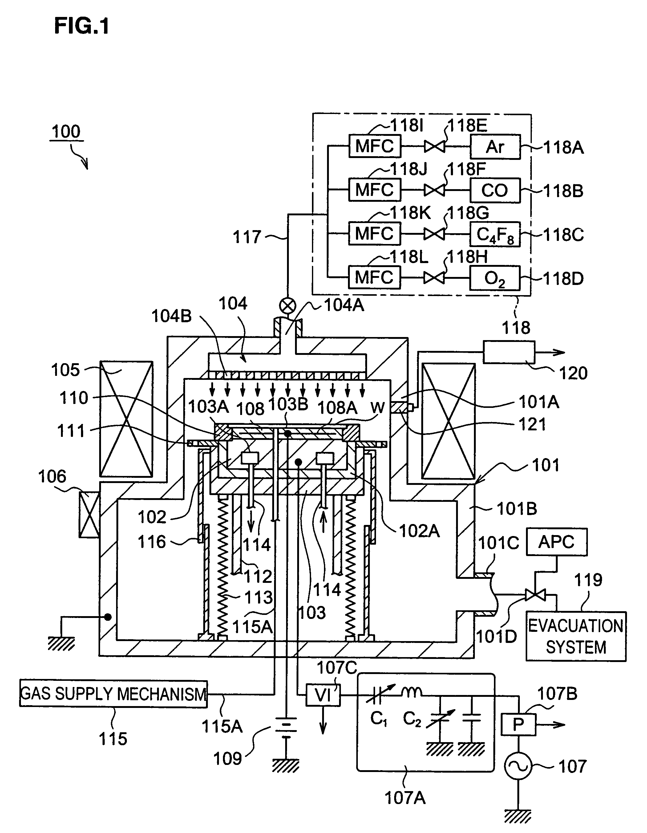
[0031]First, the plasma processing apparatus achieved in the present invention is explained in reference to FIGS. 1 and 2. The plasma processing apparatus 100 achieved in the embodiment includes an aluminum processing chamber 101, an aluminum support element 103 that supports a lower electrode 102 disposed inside the processing chamber 101 via an insulating member 102A and is allowed to move up / down, and a showerhead (hereafter, it may also be referred to as an “upper electrode” when necessary) 104 through which the process gas is supplied, disposed above the support element 103 and also used as an upper electrode.

[0032]The processing chamber 101 includes an upper chamber 101A with a small diameter located over its upper portion and a lower chamber 101B with a large diameter located over its lower portion. The upper chamber 101A is surrounded by a dipole ring magnet 105. The dipole ring magnet 105, which is formed by placing a plurality of anisotropic segment columnar magnets inside...

second embodiment

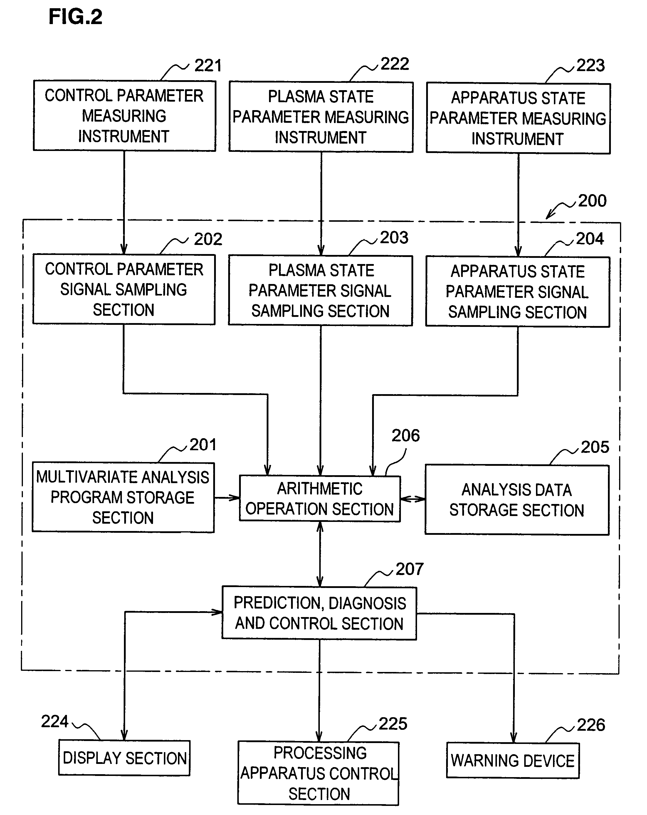
[0080]Next, the present invention is explained in reference to drawings. FIG. 3 is a block diagram schematically showing the overall structure of the control system achieved in the embodiment. A control system 300 comprises a host apparatus 310 and a plurality of plasma processing apparatuses 100A, . . . , 100N connected via a network 320. Since the structures of the plasma processing apparatuses 100A, . . . , 100N are all similar to that shown in FIG. 1, their structures are not explained in detail. The plasma processing apparatuses 100A, . . . , 100N each include the multivariate analysis section 200 such as that shown in FIG. 2. It is to be noted that the multivariate analysis section 200 and the processing apparatus control section 225 shown in FIG. 2, for instance, and a transmission / reception device 150 shown in FIG. 3 together fulfill the functions of a control device in each processing apparatus in the embodiment.

[0081]The host apparatus 310 includes at least a arithmetic op...


PUM


Abstract

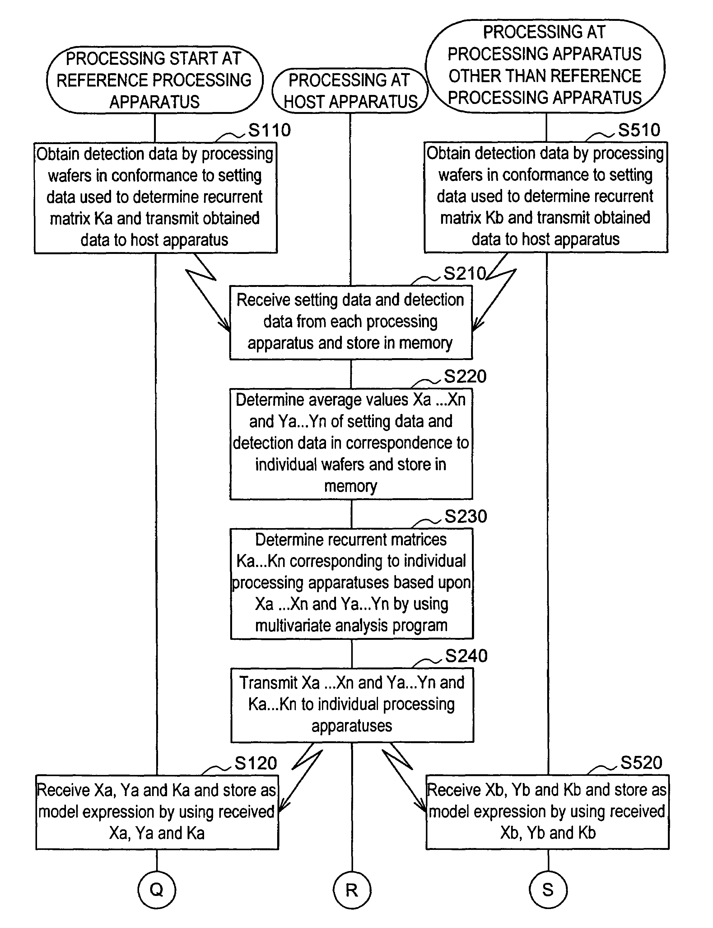
According to the present invention, multivariate analysis model expressions are generated for a plasma processing apparatus 100A and a plasma processing apparatus 100B by executing a multivariate analysis of detection data provided by a plurality of sensors included in each plasma processing apparatus when the plasma processing apparatuses 100A and 100B operate based upon first setting data. Then, when the plasma processing apparatus 100A operates based upon new second setting data, detection data provided by the plurality of sensors in the plasma processing apparatus 100A are used to generate a corresponding multivariate analysis model expression, and by using the new multivariate analysis model expression corresponding to the plasma processing apparatus 100A generated based upon the second setting data and to the plasma processing apparatus 100B, a multivariate analysis model expression corresponding to the new second setting data is generated four the plasma processing apparatus 100B.

Description

CROSS REFERENCE TO RELATED APPLICATIONS[0001]This is a continuation application of PCT International Application No. PCT / JP03 / 07132, filed Jun. 5, 2003, which claimed priority of Japanese Patent Application Nos. 2002-163869, filed Jun. 5, 2002; and 2002-168653, filed Jun. 10, 2002.BACKGROUND OF THE INVENTION[0002]1. Field of the Invention[0003]The present invention relates to a method for generating a multivariate analysis model expression for a processing apparatus, a method for executing a multivariate analysis of a processing apparatus, a control device of a processing apparatus and a control system for a processing apparatus.[0004]2. Description of the Related Art[0005]Various types of processing apparatuses are employed in semiconductor manufacturing processes. Processing apparatuses such as plasma processing apparatuses are commonly utilized during a film formation process through which a film is formed on a workpiece such as a semiconductor wafer or a glass substrate and an e...

Claims


Application Information

Patent Timeline
Patent Type & Authority Patents(United States)
IPC IPC(8): G06F7/60H01J37/32
CPCH01J37/32935
Inventor TOMOYASU, MASAYUKIOH, HINTANAKA, HIDEKI
Owner TOKYO ELECTRON LTD
Learn More