Pressure sensor package structure

a technology of pressure sensor and package structure, which is applied in the field of packaging, can solve the problems of sensor adverse effects, temperature characteristics of sensor deterioration, and failure to accurately detect pressure, so as to prevent diaphragm deformation and accurately detect pressure

Inactive Publication Date: 2009-03-24
ALPS ALPINE CO LTD
View PDF9 Cites 3 Cited by
  • Summary
  • Abstract
  • Description
  • Claims
  • Application Information

AI Technical Summary

Benefits of technology

[0009]In this structure, the adhesive area of the package body and the pressure sensor on the mount bottom surface is set to the area other than the projection area of the diaphragm of the pressure sensor. Accordingly, no adhesive agent exists below the projection area of the diaphragm of the pressure sensor. Although the difference in the thermal expansion coefficient between the material for forming the package body and the material for forming the pressure sensor becomes relatively large, the thermal expansion does not deform the diaphragm, thus preventing the diaphragm deformation under the influence other than the pressure. As a result, the diaphragm of the pressure sensor is deformed under the influence of only the pressure. This makes it possible to accurately detect the pressure.

Problems solved by technology

Assuming that the sensor is formed of silicon, which exhibits the thermal expansion coefficient of about 3 to 3.5×10⁶ / K, and the package is formed of alumina, which exhibits the thermal expansion coefficient of about 8×10⁶ / K, as the thermal expansion coefficient of the material for forming the package is larger, the sensor is adversely affected because of the influence of the thermal expansion of the package.
Thus the temperature characteristics of the sensor are deteriorated.
Especially in the case where the pressure sensor is sized to have the gap between the substrate and the diaphragm with a ga[ magnitude of several □ms, the resultant thermal expansion may deform the diaphragm, thus failing to accurately detect the pressure.

Method used


Image

  • Pressure sensor package structure
  • Pressure sensor package structure
  • Pressure sensor package structure

Examples


first embodiment

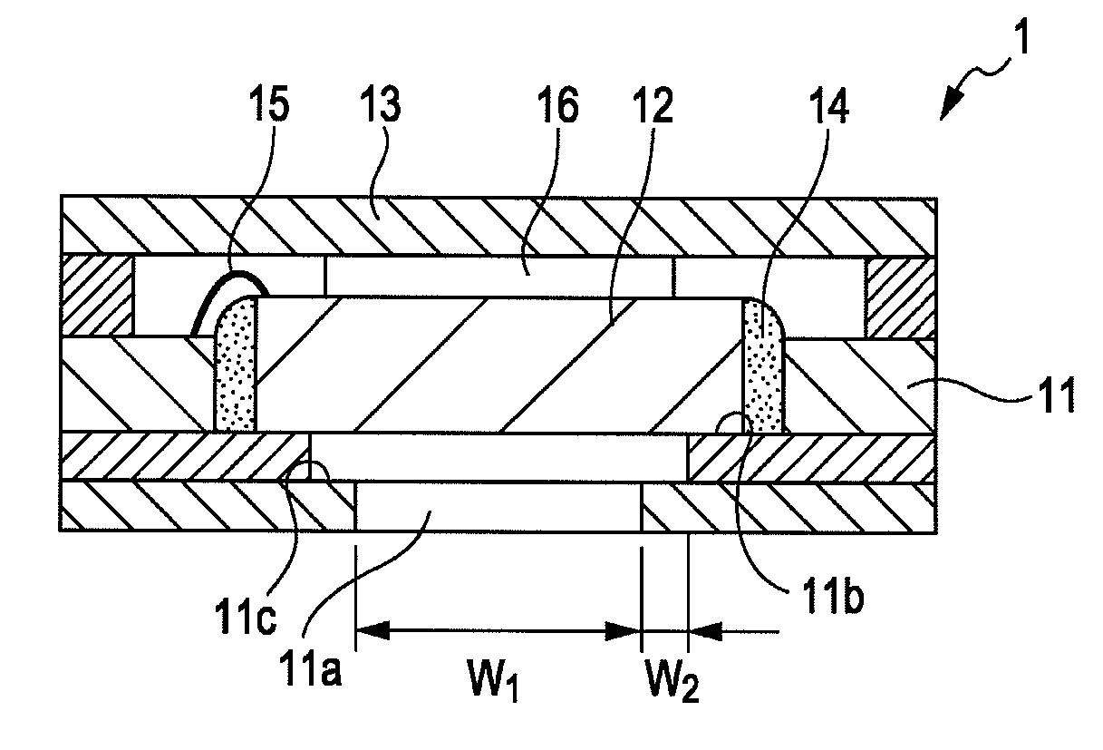
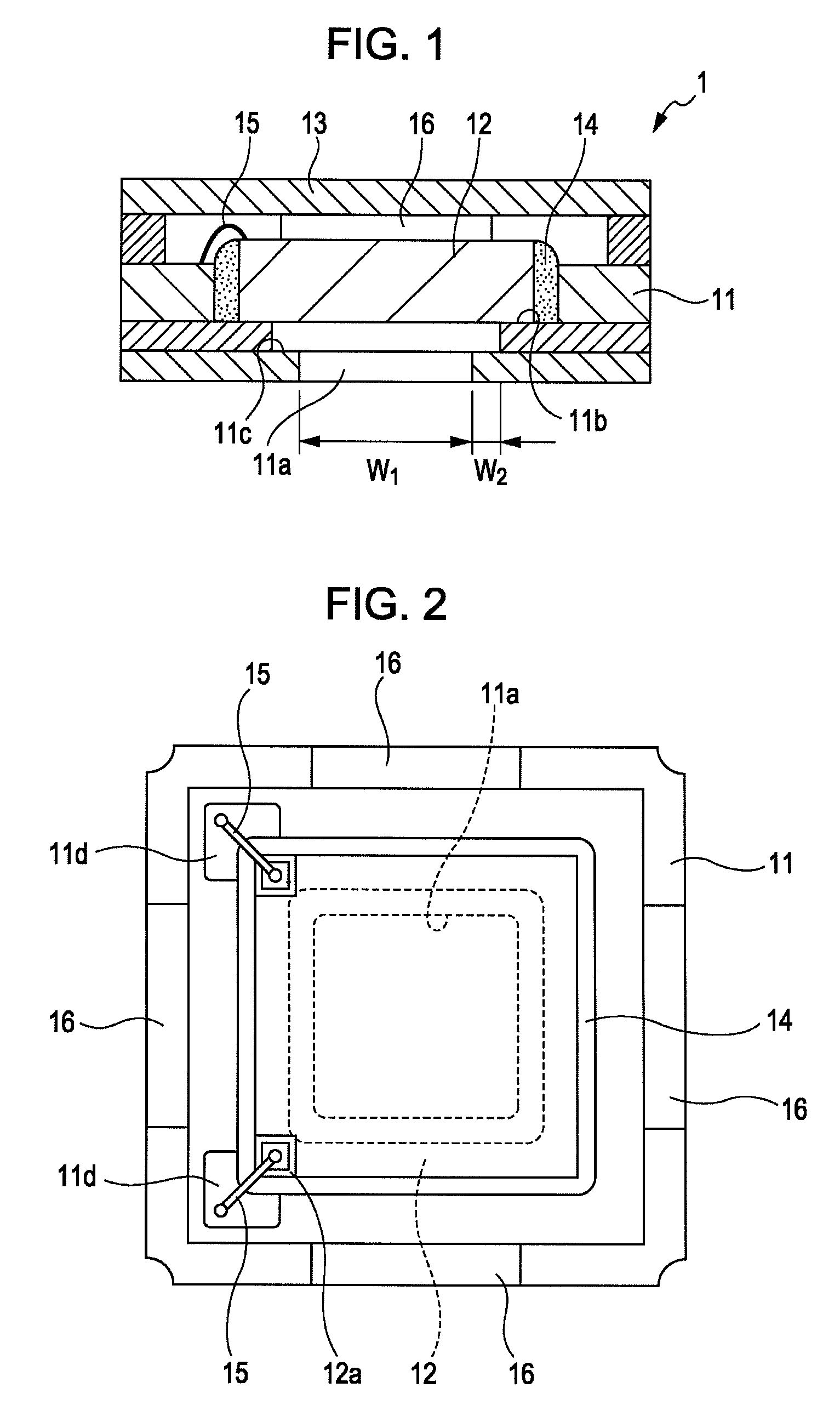
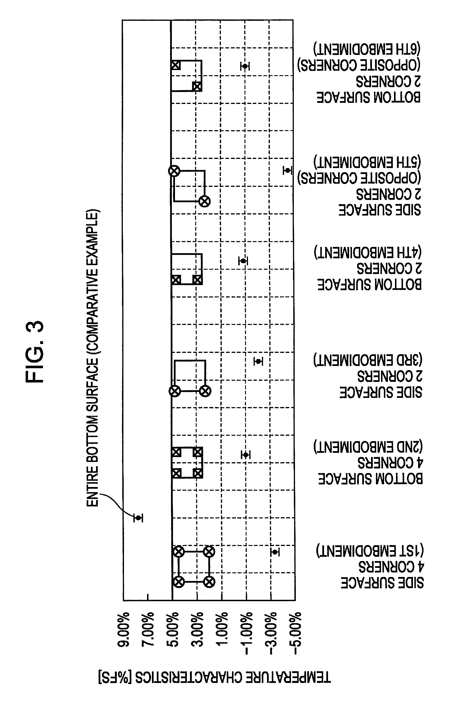
[0025]A pressure sensor is adhered to the package body at four corners of the side surface of the pressure sensor as shown in FIG. 1. The bonding pad of the pressure sensor is bonded to the conductive portion of the package body via the bonding wire. The lid member is adhered onto the upper surface of the package body. The package of the first embodiment, thus, is produced. The package body and the lid member are formed of alumina. The capacitance type pressure sensor with the diaphragm (gap: 0.3 □m) is employed as the pressure sensor. The UV cure adhesive agent is employed as the adhesive agent.

second to sixth embodiment

[0026]Packages according to second to sixth embodiments are produced, each having the same structure as that of the first embodiment except the area where the pressure sensor 12 is adhered onto the package body 11. The adhesive area in the second embodiment is set to four corners of the bottom surface of the pressure sensor 12. The adhesive area in the third embodiment is set to two adjacent corners of the side surface of the pressure sensor 12. The adhesive area in the fourth embodiment is set to two adjacent corners of the bottom surface of the pressure sensor 12. The adhesive area in the fifth embodiment is set to two opposite corners of the side surface of the pressure sensor 12. The adhesive area in the sixth embodiment is set to two opposite corners of the bottom surface of the pressure sensor 12.


PUM

PropertyMeasurementUnit
width W2aaaaaaaaaa
storage areaaaaaaaaaaa
sizeaaaaaaaaaa

Abstract

A package is mainly formed of a package body having a storage area for storing a pressure sensor, a capacity type pressure sensor stored in the storage area of the package body, a lid seals the package body in which the pressure sensor is stored, an adhesive agent for fixing the pressure sensor to the package body, and a bonding wire for electrically coupling a bonding pad of the pressure sensor and a conductive portion of the package body. An adhesive area of the package body and the pressure sensor is set to the area other than a projection area of the diaphragm of the pressure sensor on a mount bottom surface. This makes it possible to provide the package for the pressure sensor capable of detecting the pressure with high sensitivity although the gap between the substrate and the diaphragm has the value with the magnitude of several μms.

Description

CLAIM OF PRIORITY[0001]This application claims benefit of the Japanese Patent Application No. 2006-271001 filed on Oct. 2, 2006, which is hereby incorporated by reference.BACKGROUND[0002]1. Field of the Invention[0003]The present invention relates to a package for storing a pressure sensor such as a capacitance type pressure sensor.[0004]2. Description of the Related Art[0005]Recently, a capacitance type pressure sensor and a piezo type pressure sensor have been developed to be mounted on various types of the devices. Normally, this type of sensor is required to be packaged with a ceramic package and the like so as to be mounted on the device.[0006]For example, for the purpose of packaging the pressure sensor, an adhesive agent (die bonding agent) is applied over an entire bottom surface of the package, on which the pressure sensor is mounted and adhered (die bonded) on the bottom surface of the package with the adhesive agent, for example as disclosed in Japanese Unexamined Patent ...

Claims


Application Information

Patent Timeline
Patent Type & Authority Patents(United States)
IPC IPC(8): G01L7/00
CPCG01L19/0069G01L19/147H01L2224/48091H01L2924/16195H01L2924/00014
Inventor FUKUDA, TETSUYAKIKUIRI, KATSUYASATO, KIYOSHIWATANABE, MITSURUNAKAMURA, YOSHINOBU
Owner ALPS ALPINE CO LTD
Why Eureka
Try Eureka