Tine raking device

a raking device and a technology for unwanted debris, applied in the field of unwanted debris separation, can solve the problems of unnecessary removal of sand, and achieve the effects of reducing the amount of sand adhering, facilitating the subsequent separation of debris and sand, and further enhancing the separation process

Active Publication Date: 2009-03-24
H BARBER & SONS
View PDF58 Cites 5 Cited by
  • Summary
  • Abstract
  • Description
  • Claims
  • Application Information

AI Technical Summary

Benefits of technology

[0009]In its narrower aspects, the present invention embodies a perforated conveyor mechanism. The perforations allow residual sand removed with the debris to be further separated during the debris transfer up the elevating travel of the conveyor belt so as to allow the sand and small soil-like material to be returned to the ground. The outer surface of the conveyor belt does not include cross bars conventionally used for securing tines to the conveyor belt. Cross bars on the outer surface of the conveyor belt are part of the current technology and are eliminated herein to allow the free flow of debris between tines and down the conveyor. Moreover, the base of the tines including a coil or other flexible section is recessed relative to the outer surface of the conveyor belt to further facilitate the flow of debris down the elevating portion of the conveyor.
[0015]Increasing the height of the moldboard relative to the tines reduces the volume of material which must be carried in front of the board to level the beach. This in turn reduces the force required to level the beach. A smaller towing unit with less horse power is required resulting in increased fuel economy and a reduction in the cost of the towing unit.

Problems solved by technology

When this is done with the current technology the amount of sand and small debris picked-up is increased resulting in the unnecessary removal of sand.

Method used


Image

  • Tine raking device
  • Tine raking device
  • Tine raking device

Examples


Embodiment Construction

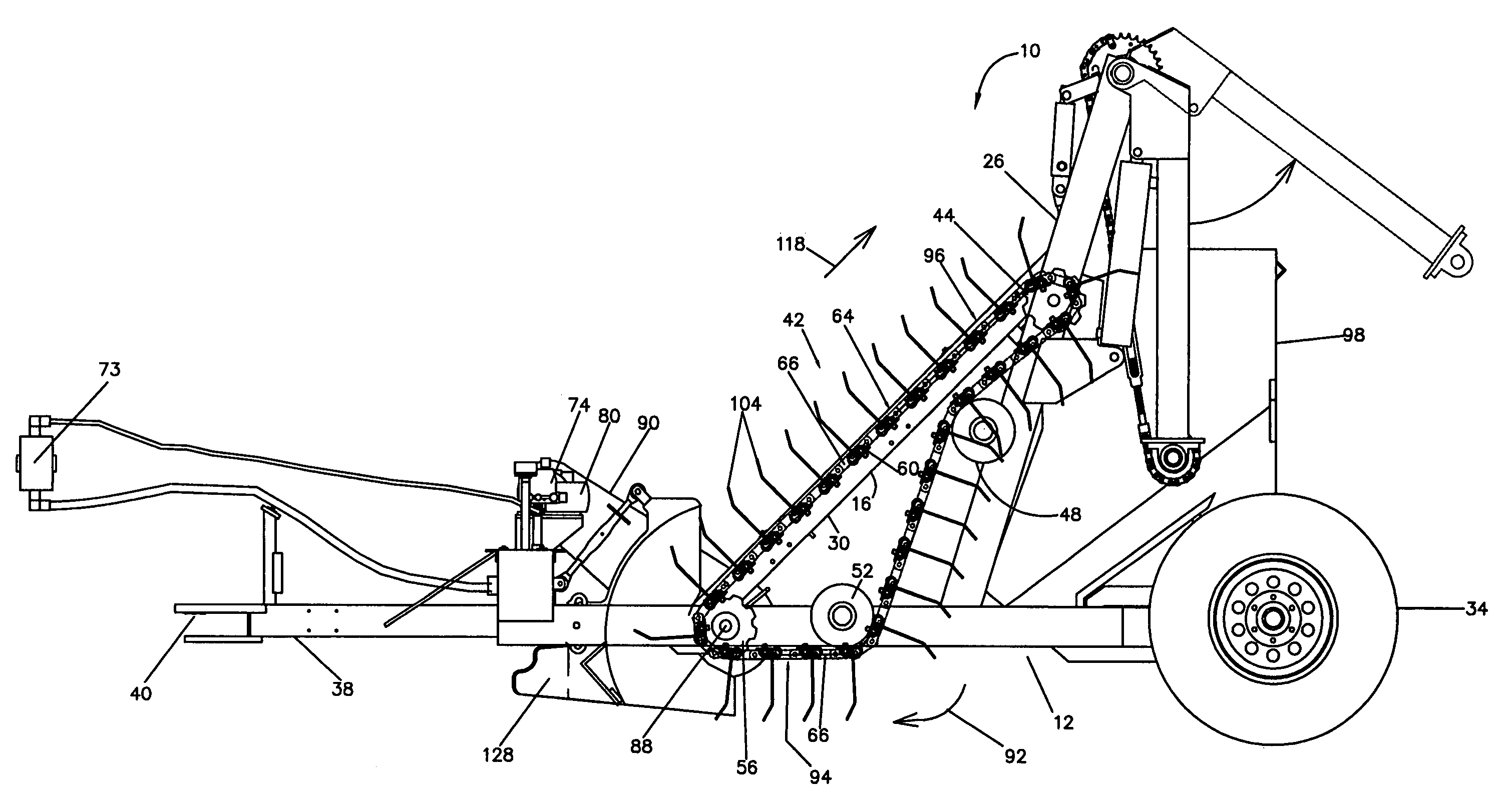
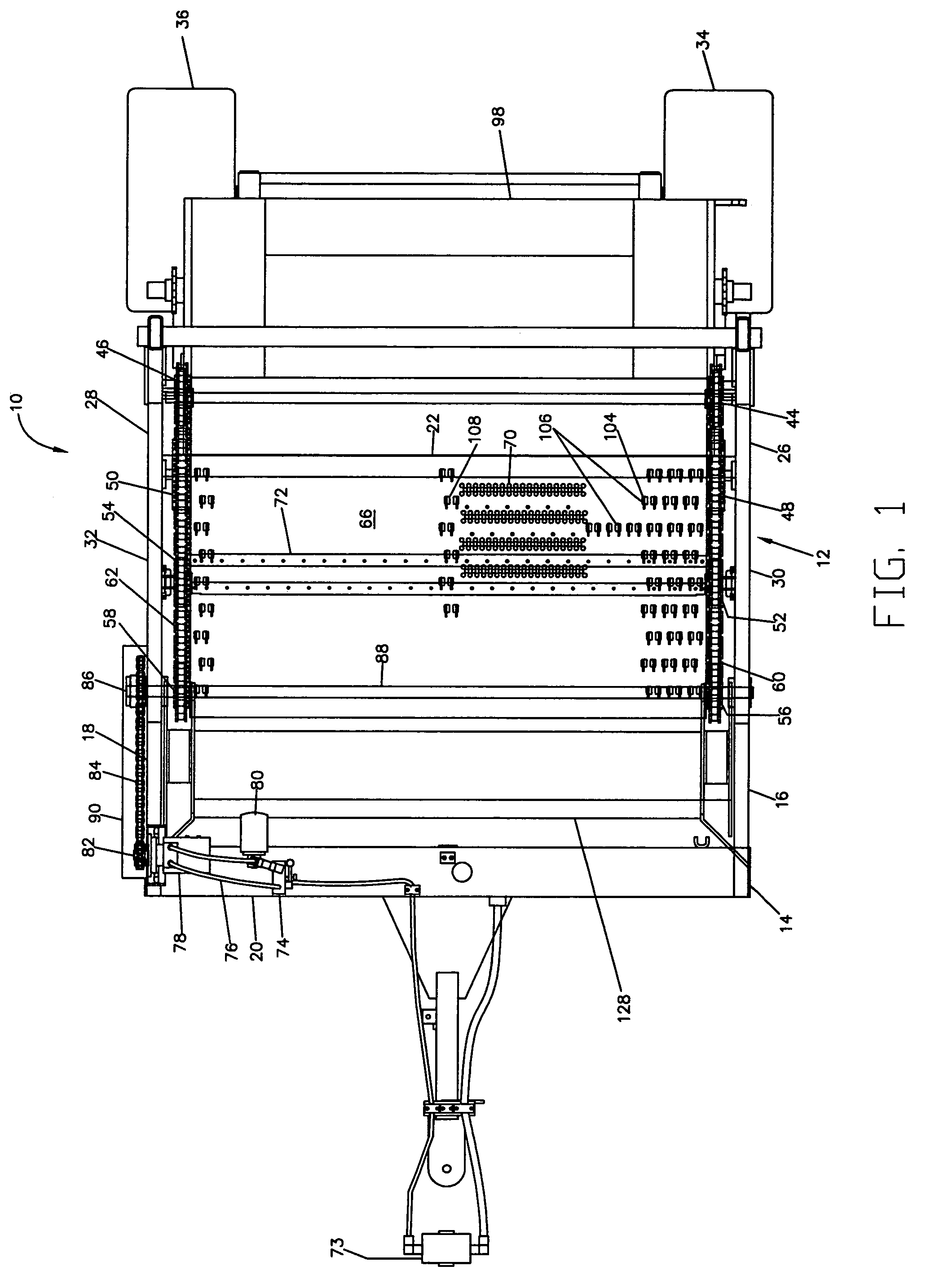
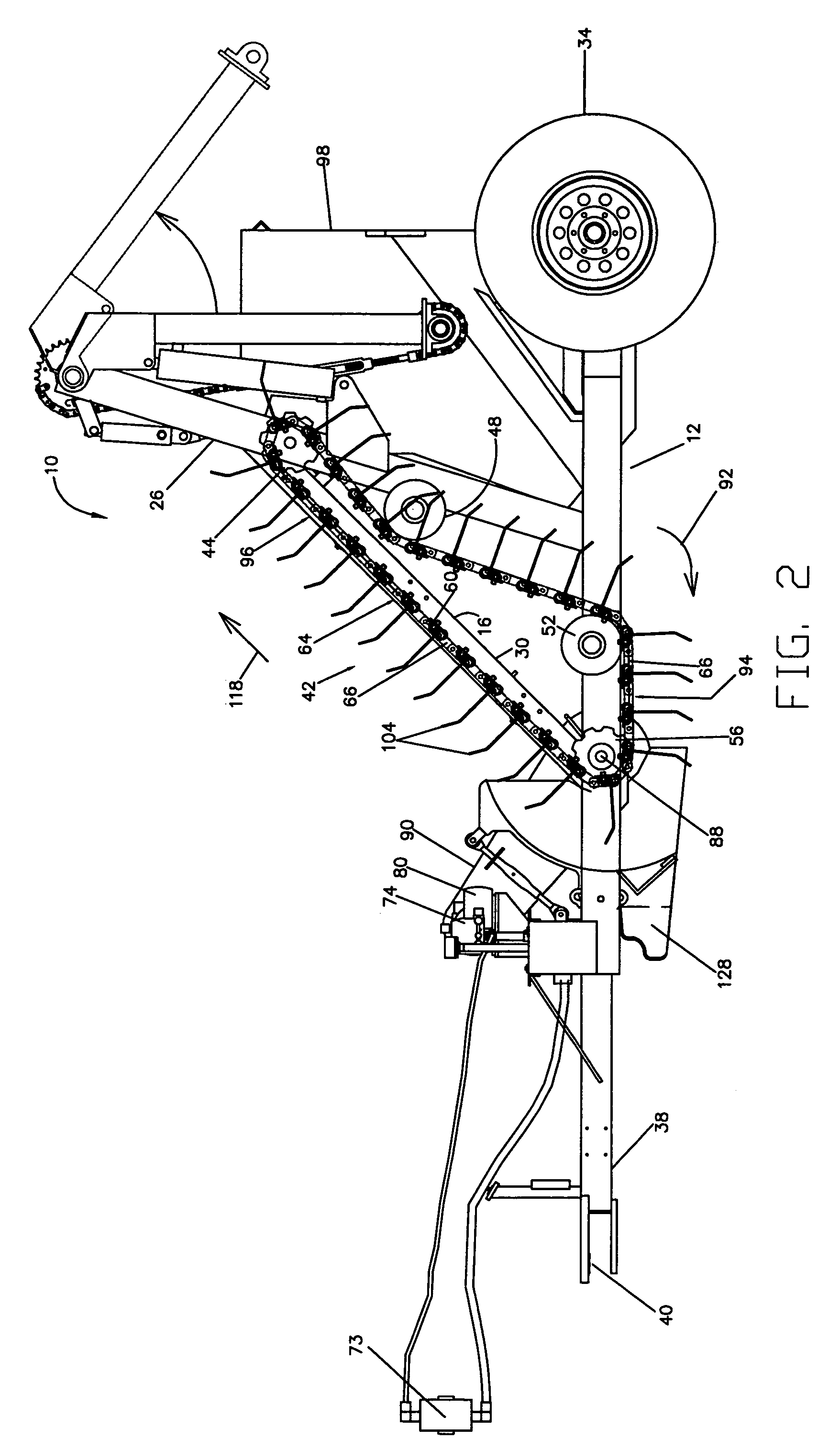
[0023]With reference to FIG. 1 and 2, a tine raking device embodying the present invention is generally indicated by the reference number 10. The device 10 includes a generally rectangularly shaped, perimetric base frame 12 suitably formed of beam members generally designated 14 such as angle, channel iron or tubing. The frame 12 has a pair of spaced side frame members 16 and 18 that are terminally bridged by front and rear frame members 20 and 22 respectively. A pair of generally triangularly shaped conveyor frame assemblies formed of rectangular tubing are mounted upon a rear half of the side frame members 16 and 18 and extend upwardly therefrom. The conveyor frame assemblies include an upwardly or generally vertically disposed conveyor frame members 26 and 28 mounted at a rear of each of the side frame members 16, 18. The conveyor frame assemblies also include generally angularly disposed brace members 30 and 32 respectively coupled at one end to the conveyor frame members 26 and...


PUM


Abstract

A tine raking device includes a frame and a conveyor assembly supported on the frame. The conveyor assembly has a conveyor belt defining perforations sized to allow passage therethrough of granules of sand and to prevent passage therethrough of larger sized debris to be removed from a ground surface. Flexible tines extending outwardly from the conveyor belt. The tines are arranged in rows across a width of the conveyor belt. The rows each are longitudinally spaced from adjacent rows along the conveyor belt such that a generally unimpeded path is defined along an outer surface of the conveyor belt for debris to flow between adjacent tines along an associated row. The conveyor assembly includes a lower section for permitting the tines to contact and remove debris from a ground surface being cleaned, and an inclined section for lifting debris on the conveyor belt away from the ground surface being cleaned.

Description

FIELD OF THE INVENTION[0001]This invention relates generally to the separation of unwanted debris from soil or the like, and more particularly relates to a an improved device for cleaning sand bathing beaches or sand-like tracts of unwanted refuse, litter and other types of debris.BACKGROUND OF THE INVENTION[0002]The littering propensities of the general public at beaches and other sandy recreation areas appears to be unlimited as to both the quantity and character of the refuse and litter involved and, also, wholly uncontrollable from any practical standpoint. The unavoidable accumulation of such refuse or debris, when coupled with the accumulation of naturally originating debris such as sea grasses, oversized shells, marine residues, and other and varied water deposited material, has created ever increasing problems for those responsible for the maintenance of cleanliness at such locations. The continually increasing magnitude of such problem with the attendant economic aspects of...

Claims


Application Information

Patent Timeline
Patent Type & Authority Patents(United States)
IPC IPC(8): A01D17/00
CPCE01H12/00
Inventor BARBER, JOHN H.BARBER, JAMES P.
Owner H BARBER & SONS
Why Eureka
Try Eureka