
Door with sliding door leaf and with guide means

Inactive Publication Date: 2009-03-24
INVENTIO AG
View PDF21 Cites 5 Cited by
  • Summary
  • Abstract
  • Description
  • Claims
  • Application Information

AI Technical Summary

Benefits of technology

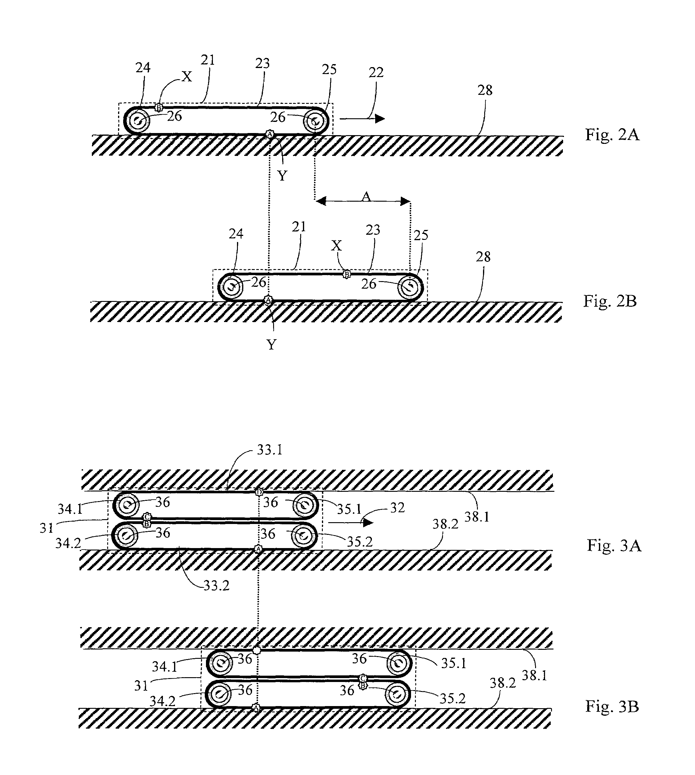
[0006]It can be advantageous to provide one or more guide elements for the belt in order to align the belt at the guide surface. During sliding of the door leaf, the belt is so aligned by the guide elements that a portion of the belt bears against the guide surface and the belt runs over at least one of the guide elements. The guide means in that case guide the door leaf along the guide surface and impart stability to the leaf.
[0023]The door can have, apart from the stated guide surface and the stated guide means, a further guide surface and further guide means which are so arranged that the door is guided in both directions transversely to the door leaf. In this manner there can be realized a guidance of the door leaf which is free of play transversely to the direction of movement. A door with a door leaf which is guided with no or only little play can be sealed particularly effectively, since zones, which are permeable to air, in the region of the guide can be substantially reduced or entirely avoided.

Problems solved by technology

Apart from the fact that air currents of that kind can feel unpleasant, disturbing noises also thereby result.
In addition, in the case of insufficient sealing of an elevator shaft smoke can propagate over several floors.

Method used


Image

  • Door with sliding door leaf and with guide means
  • Door with sliding door leaf and with guide means
  • Door with sliding door leaf and with guide means

Examples


first embodiment

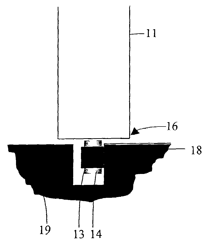
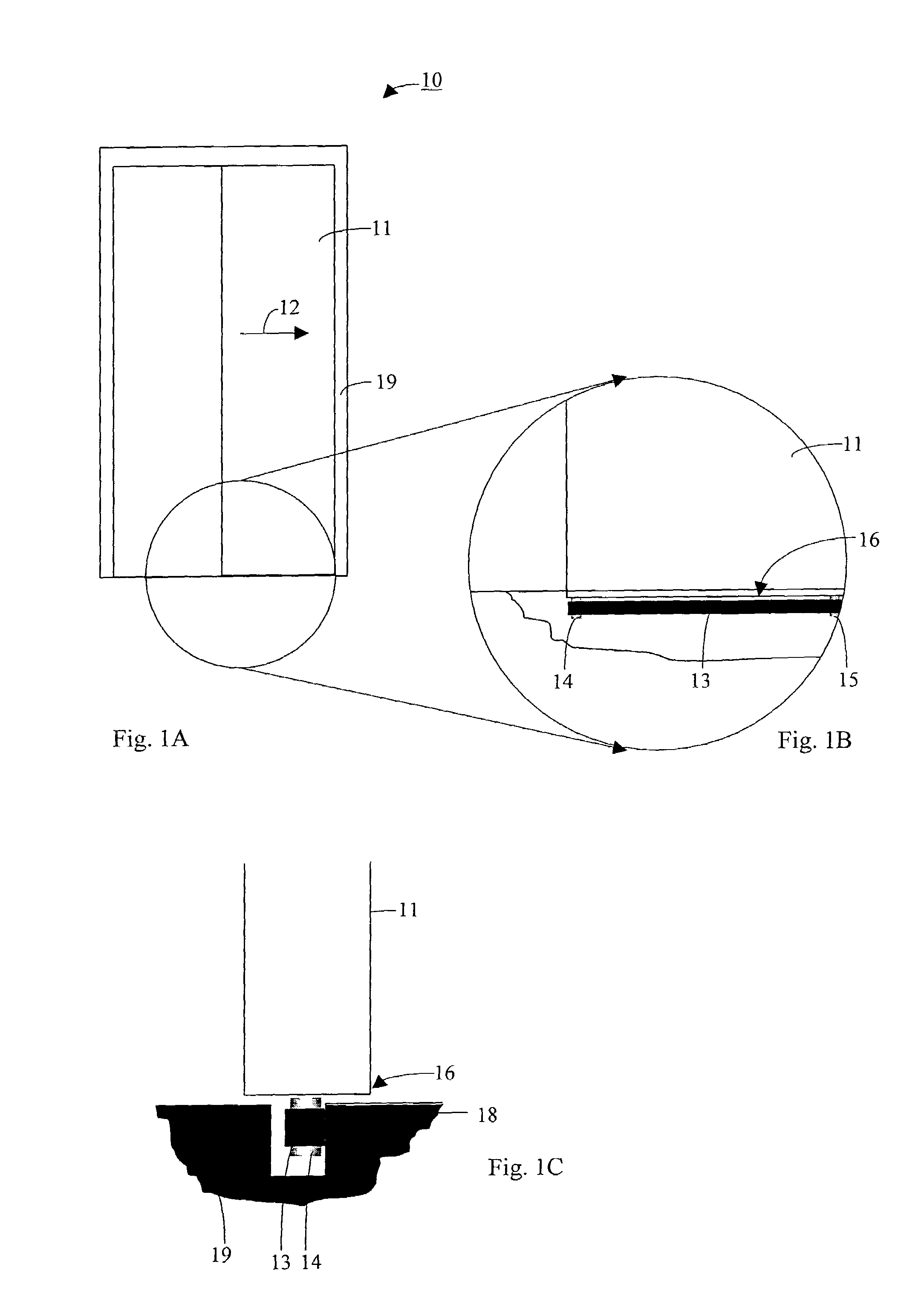
[0038]the present invention is described in conjunction with FIGS. 1A to 1C. A door 10, which forms a shaft door of an elevator (not shown), is shown. The door 10 comprises at least one frame 19 and a door leaf 11 that is slidable in a direction 12 of sliding relative to the frame 19. Arranged at the frame 19 is a vertical guide surface 18 (see FIG. 1C) at which the door leaf 11 is to be guided. The door 10 comprises guide means that are arranged in the region of a lower edge 16 of the door leaf 11. The guide means comprise a (resilient) belt 13 and guide elements 14 and 15, which are arranged at the door leaf 11 and around which the belt 13 runs.

[0039]The belt 13 is so aligned by the guide elements 14, 15 that it extends by its belt length parallel to the direction 12 of sliding of the door leaf 11. A surface of the belt 13 bears flatly against the guide surface 18 when the door 11 is open, closed and sliding. In addition, the door leaf 11 can have a suspension (not shown) in the u...

third embodiment

[0045]FIG. 4 shows a detail of a door according to the present invention. A door leaf 41 has a groove going out from its lower edge. Fastened in the region of this groove by way of roller bearings 45 is a guide element 44 in the form of a deflecting roller, which is rotatable about a vertical axis (not illustrated). The guide element 44 substantially consists of a belt guide portion 44.1, a lower end plate 44.2 and an upper portion 44.3 in the region of the roller bearings 45. A belt 43, the belt width of which extends in vertical direction, runs around the belt guide portion 44.1 of the guide element 44. The belt guide portion 44.1 forms, between the larger diameter end plate 44.2 and the larger diameter upper portion 44.3, a groove-like depression at the surface of the guide element 44. This depression forms a guide structure for the belt, which ensures lateral guidance of the belt 43 during running of the belt 43 around the guide element 44.

fourth embodiment

[0046]FIGS. 5A and 5B show the door according to the present invention, with a door leaf 61. FIG. 5A shows the door leaf 61 in a first position, and FIG. 5B in a second position in which the door leaf 61 is displaced opposite to the first position over a path A. The guide means comprise an open belt 63 and two guide elements 64, 65 at the door leaf 61. The first guide element 64 is a longitudinal guide for a first belt end 63.1, which extends in the sliding direction of the door leaf 61. The second guide element 65 is a deflecting element or a deflecting roller. The belt 63 is fastened by its second belt end 63.2 at or in the region of the frame (not illustrated).

[0047]Spring elements (not shown) can be used which ensure a pressing pressure of the belt in the direction of the guide surface and / or produce a bias of the belt.

[0048]Other forms of guide elements can be used instead of deflecting rollers that rotate about an axis. Particularly suitable, for example, are “Nylon” guide ele...


PUM


Abstract

A door with a sliding door leaf has guides that are arranged in the region of an edge of the door leaf. The guides include a belt so aligned that it extends by the belt length thereof longitudinally of the guide surface for the door leaf in the direction of sliding of the door leaf. When the door leaf is sliding, the belt runs with the door leaf in such a manner that a portion of the belt bears against the guide surface when the door leaf is open, closed and sliding and thereby guides the door leaf.

Description

BACKGROUND OF THE INVENTION[0001]The present invention relates generally to a door with a sliding door leaf and an elevator installation with such a door.[0002]Doors with sliding door leaves, which are also termed sliding doors, have numerous advantages; in particular, their need for space relative to the need for space of swinging doors is comparatively small, since the opening door leaves slide parallel to and in the immediate vicinity of the wall and thus do not demand any usable space in the region of the door opening.[0003]The disadvantages of such doors with sliding door leaves reside particularly in that: the door leaves are not, or not sufficiently, guided and produce noises during their sliding, which can frequently be heard in remote areas of the building; the guide elements which serve for guidance of the door leaves during sliding thereof are subject to considerable wear; and the door leaves in closed state form only an unsealed or poorly sealed separation of the spaces ...

Claims


Application Information

Patent Timeline
IPC IPC(8): B66B13/24B66B13/28E05D13/00E05D15/06E05D15/16E05F11/00B66B13/30
CPCE05D15/0656E05Y2900/132
Inventor SPIESS, PETER
Owner INVENTIO AG
Learn More