
Threaded joint for pipes provided with seal

a technology of thread threaded joints and pipes, which is applied in the direction of screw threaded joints, non-disconnectible pipe joints, bracing pipes, etc., can solve the problems of leakage of pipes, affecting the tightness of joints, and limiting the contact pressure, so as to achieve fine pipe wall thickness and adequate rigidity

Active Publication Date: 2009-03-24
TENARIS CONNECTIONS
View PDF21 Cites 43 Cited by
  • Summary
  • Abstract
  • Description
  • Claims
  • Application Information

AI Technical Summary

Benefits of technology

The present invention is about a threaded joint for pipes that has improved sealing and maintains rigidity, especially in cases where the pipe wall is thin. The joint also has better resistance to high loads without affecting the seal. The invention achieves this by producing a joint with a male and female member, with seal surfaces that generate a metal-metal type joint seal. A reinforcement section is positioned at the end of the female member, which has a larger internal diameter than the first member. The joint seal device is designed to balance various needs, such as minimum overall dimensions, maximum structural resistance, and conservation of seal capacity. The dimensions chosen for the joint allow for good resistance to both axial and radial loads.

Problems solved by technology

The results of said loads are particularly negative when they tend to separate the male and female members, eliminating the contact between the seal surfaces and therefore affecting or destroying tightness, causing a leak in the pipe.
Nevertheless a problem that occurs in designing seal surfaces of the type in which there is metal-metal contact for the joints is that of not exceeding the contact pressure limit.
On the other hand, however, if the value of said interference remains insufficient, the tightness of the joint could be affected when subject to high pressure.
Said expansion is even more marked if high traction loads occur, resulting even in plastic deformation of the metal in the seal surface area.
The efficiency of the seal therefore depends heavily on this phenomenon and, in particular, the pipe may not be suitable to withstand the external pressure once it has been subjected to particularly high internal pressure.
This can therefore cause the formation of a leak in the pipe with possible losses.
A breakage, especially after the pipes have been positioned underground, therefore making it practically impossible for the operators to intervene directly on any joint that breaks, can have extremely serious financial consequences for the extraction plant in addition to causing considerable environmental damage, particularly if the reservoir contains aggressive elements.
Both solutions, however, involve a considerable increase in production costs.

Method used


Image

  • Threaded joint for pipes provided with seal
  • Threaded joint for pipes provided with seal

Examples


Embodiment Construction

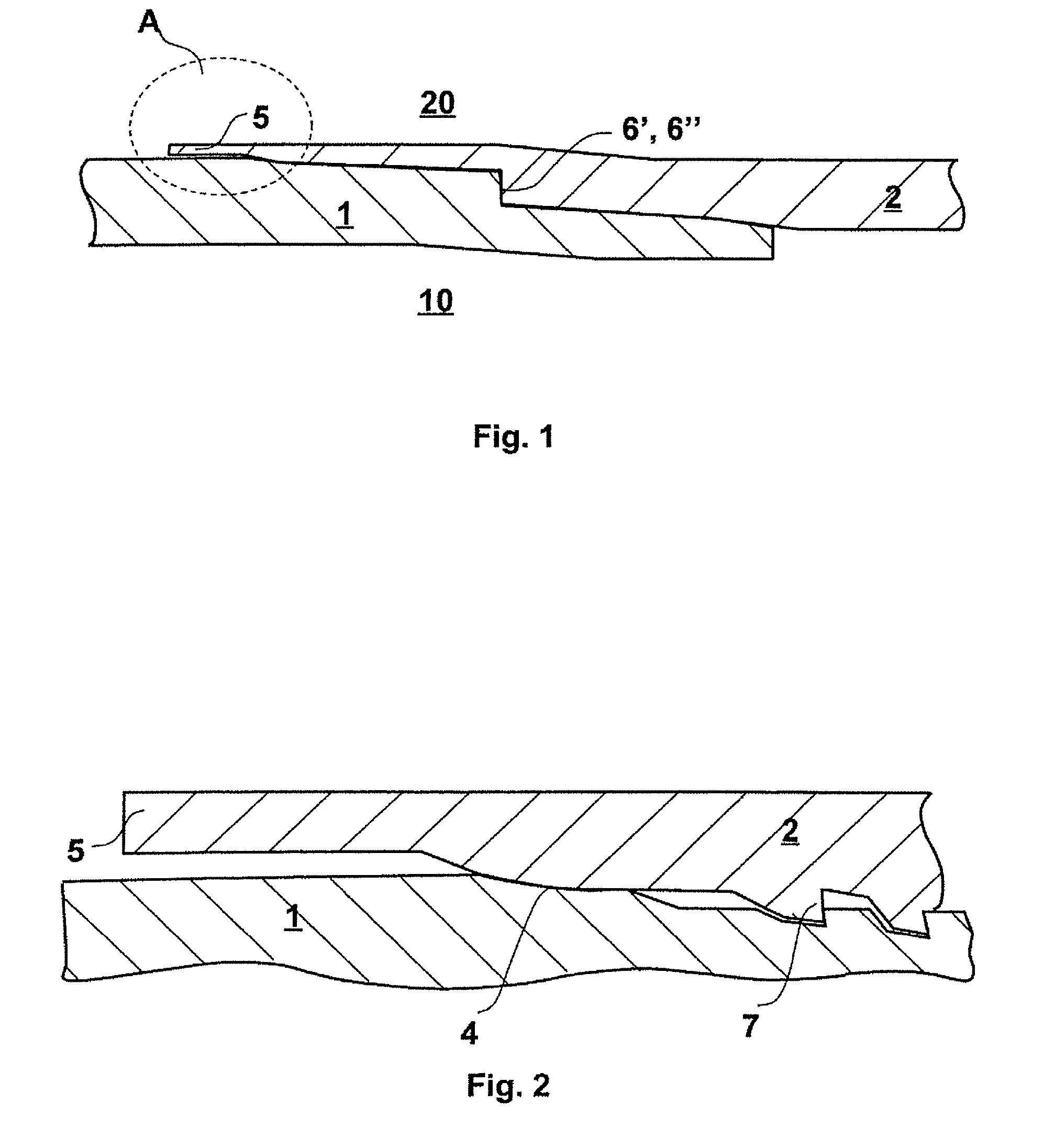
[0020]With reference to the figures, the threaded joint comprises two members, the segments of pipe, in which one is the male member 1 or “pin” and the other is the female member 2 or “box”. The joint defines an internal part 10 in which the fluid flows, for example natural gas or crude oil or other similar fluid, and an external part 20 which can also be lapped by fluids or other liquids of various nature, generally under pressure, or only causing hydrostatic loads.

[0021]The threaded joint advantageously provides for a seal in the external part in which tightening is produced during reciprocal making up of the pin 1 and box 2, by means of interference of two circumferential sections of the metal surfaces. In the female member 2 the circumferential section or seal surface 4, contributing to constitution of the seal device, is internal to the wall of the pipe, appropriately sized and positioned at a pre-set distance from the initial section of the female thread 7.

[0022]The seal surfa...


PUM


Abstract

A threaded joint for pipes comprising at least one seal of the metal-metal interference type arranged externally to the female thread. The joint has an extension of the box beyond the seal which produces an elastic tightening band effect on the seal so that excessive interference on the seal is not necessary, thus favoring correct making up.

Description

FIELD OF THE INVENTION[0001]The present invention relates to a joint for pipes, in particular to a joint for pipes used in the extraction / injection of fluids, for example oil or gas, provided with a seal device.STATE OF THE ART[0002]In the natural gas and oil extraction industry, segments of pipes of a pre-defined length are used which must be joined together at their end to reach the considerable depths at which the reservoirs of hydrocarbons are generally found. During drilling the wells are lined with metal pipes throughout their length. The segments of metal pipe, generally approximately ten meters or so long, are screwed together by means of threaded joints. To cover the entire depth of the well numerous strings are also used which have, for reasons connected with the mechanical resistance and the geological characteristics of the formation, decreasing diameter the greater the depth reached by the string, so as to constitute a “telescopic” type structure.[0003]Once drilling has...

Claims


Application Information

Patent Timeline
Patent Type & Authority Patents(United States)
IPC IPC(8): F16L15/00F16L13/14
CPCF16L15/004
Inventor CARCAGNO, GABRIEL E.MOROTTI, MATTEO
Owner TENARIS CONNECTIONS
Learn More