Gas burner-type combustion device and method for operating same

a combustion device and burner type technology, applied in combustion types, combustion methods, combustion using lumps and pulverizing fuels, etc., can solve problems such as awkward external environment, increase or reduce the strength or shape of flames, increase or reduce the detection foliar spectrum

Active Publication Date: 2009-03-24
FRANCONE NEE JAULENT AUDREY MARJORY +2
View PDF27 Cites 5 Cited by
  • Summary
  • Abstract
  • Description
  • Claims
  • Application Information

AI Technical Summary

Benefits of technology

[0015]Thus, the bursting of the flux being produced even though the mix is not as yet inflamed, that being on the inside of the burner, this operation not being subject to the uncertainties of the external environment which could be particularly awkward if the flame were to be burst at the outlet of the burner.
[0024]This feature is particularly advantageous in that it guarantees an optimised management of the consumption of the gas and therefore allows to save on it as and when possible.

Problems solved by technology

Thus, the bursting of the flux being produced even though the mix is not as yet inflamed, that being on the inside of the burner, this operation not being subject to the uncertainties of the external environment which could be particularly awkward if the flame were to be burst at the outlet of the burner.

Method used


Image

  • Gas burner-type combustion device and method for operating same
  • Gas burner-type combustion device and method for operating same
  • Gas burner-type combustion device and method for operating same

Examples


Embodiment Construction

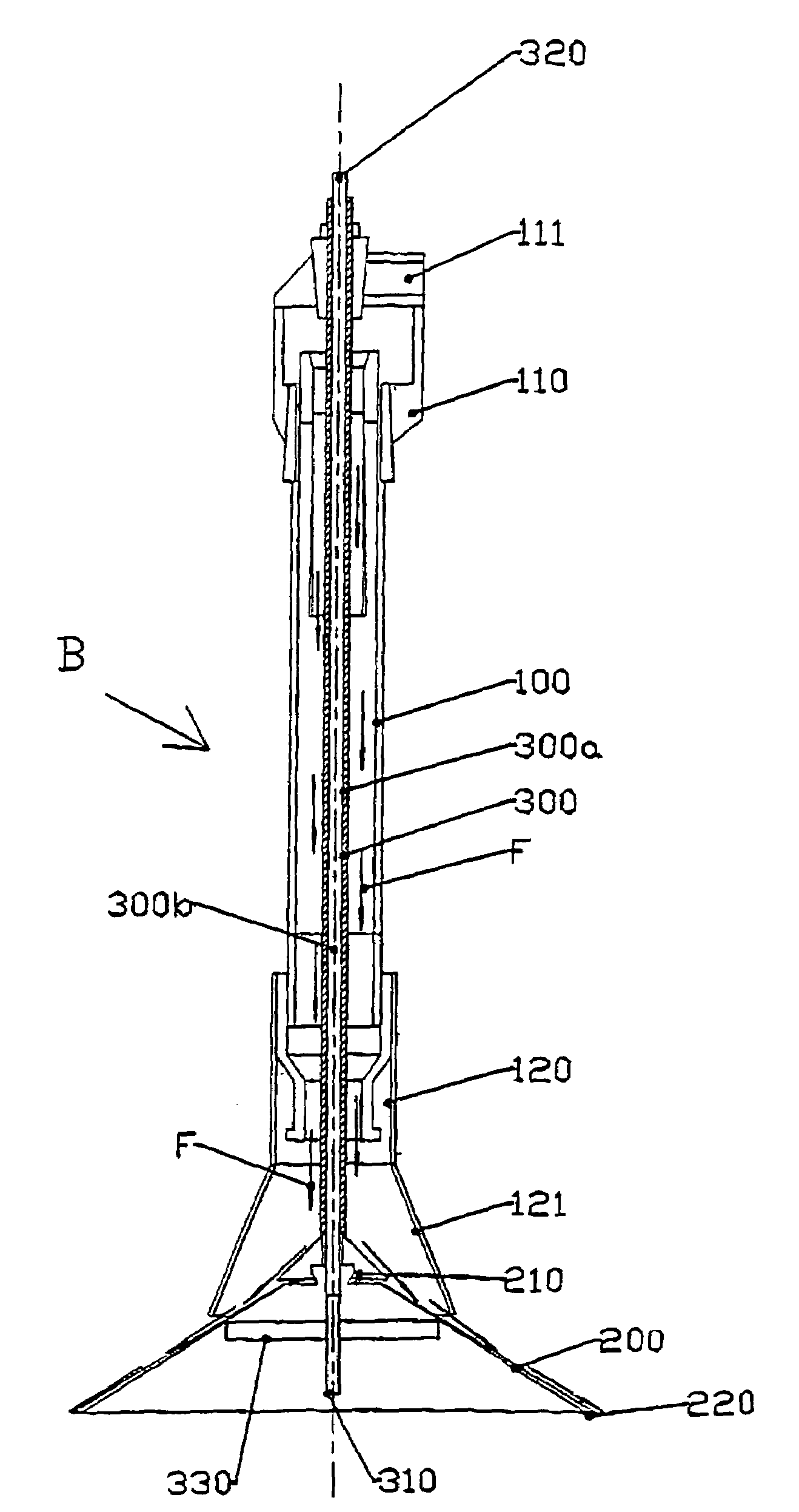
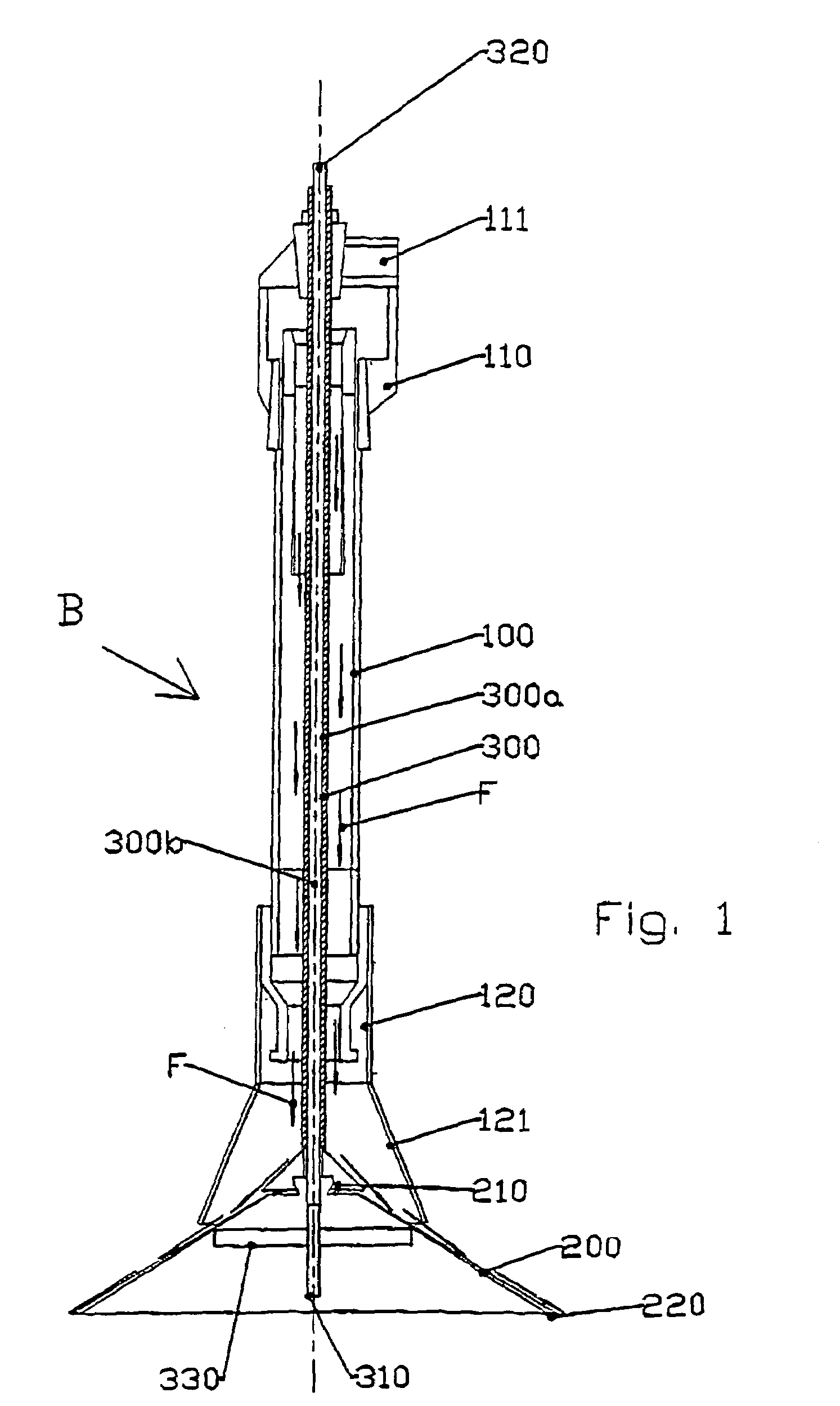
[0031]As illustrated in FIG. 1, the gas burner type device called “burner” marked B comprises as a whole unit a cylindrical hollow body 100, whose upper end 110 is fitted with a gas inlet in the form of a coupling 111 and whose lower end 120 opens out to allow the inflamed gas and air mix to escape. The path the gas takes is symbolised by the arrow F.

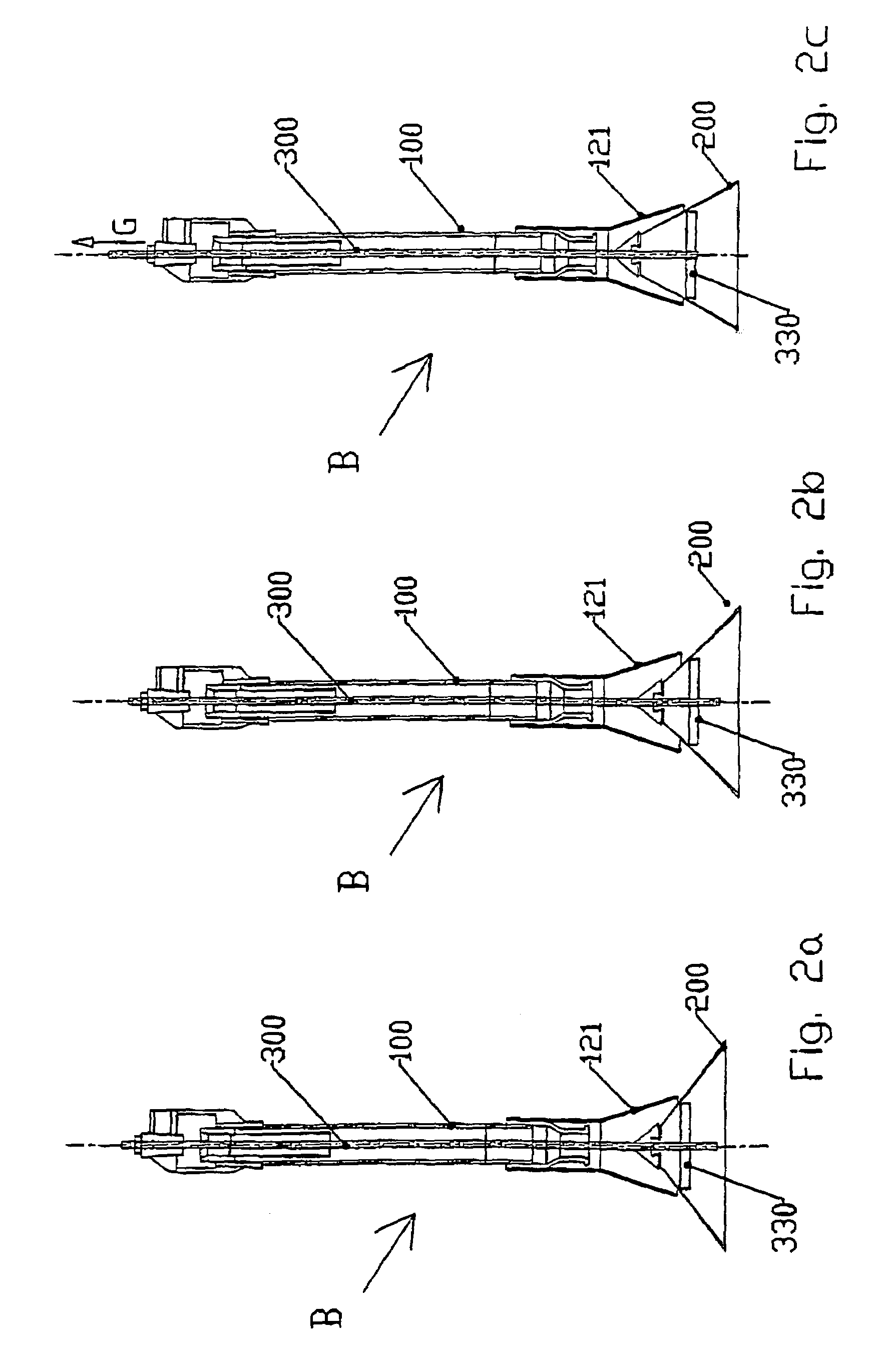
[0032]According to the invention, the burner B comprises a diffusion cone 200 whose tip 210 is located upstream from the flame creation zone so as to ensure the bursting of the, not as yet inflamed, air and gas mix. Thus, the flux of the gas and the air is burst on the inside of the burner B so that this operation is not hindered by the external constraints thus guaranteeing a good distribution of the flames.

[0033]According to the invention, this cone 200 is movable and co-operates with a fixed nozzle tip 121 equipping the lower end 120 of the burner B equipped with the diffusion cone participating in the diffusion of the flames so that...


PUM


Abstract

The present invention concerns a gas burner type combustion device called “burner” (B) projecting a mix of air and gas inflamed at the outlet of a pipe. The gas burner is fitted with a movable diffusion cone (200) whose tip (210) is located at least upstream from the flame creation zone so as to ensure the bursting of the air and gas mix, the relative displacement of the cone (200) according to the axis of diffusion defined by the flames allowing to adjust the strength of the latter.

Description

CROSS REFERENCE TO RELATED APPLICATION[0001]This application is a national stage of PCT / FR2003 / 002003 filed Jun. 27, 2003 and is based upon French Patent Application No. 02 / 07983, filed Jun. 27, 2002 under the International Convention.BACKGROUND OF THE INVENTION[0002]1. Field of the Invention[0003]The invention falls within the field of gas burner type combustion devices and more precisely to adaptations allowing to adjust the intensity and the form of the generated flame.[0004]2. Related Art of the Invention[0005]The applicant has noticed that various devices concerning the field of burners within the scope of thermal weed killing have inconveniences of which the main one are detailed below.[0006]The gas burners disclosed in the French patents FR2752145, FR2792499 and FR2793415, constitute the basis of leaf-stripping and / or thermal disinfecting devices.[0007]It would appear that these burners do not allow the actual and efficient working zone of the flames generated by the burner t...

Claims


Application Information

Patent Timeline
Patent Type & Authority Patents(United States)
IPC IPC(8): F23C5/06A01M15/00A01M21/04F23D14/84
CPCA01M15/00A01M21/04F23D14/84
Inventor JAULENT, GERARD
Owner FRANCONE NEE JAULENT AUDREY MARJORY
Why Eureka
Try Eureka