Radiolucent skull clamp with removable pin load applicator

a clamping device and radiolucent technology, applied in the field of neurosurgical devices, can solve the problems of increasing the envelope of space required by the skull clamping device within the scanning machine, making the information more difficult to interpret and use, and achieves the effect of reducing the envelope of space and easy setting the desired engagement for

Active Publication Date: 2009-03-24
INTEGRA LIFESCI
View PDF16 Cites 41 Cited by
  • Summary
  • Abstract
  • Description
  • Claims
  • Application Information

AI Technical Summary

Benefits of technology

[0008]The present invention provides a skull pin assembly and removable pin load applicator that allows a user to easily set a desired engagement force but is fully radiolucent during an MRI scan. Further, the removable pin load applicator includes the force adjusting screw and can be removed after the engagement force is set, thereby substantially reducing the envelope of space required by the skull clamp within the scanning machine.
[0009]According to the principles of the present invention and in accordance with the described embodiments, the invention provides a skull pin assembly slidably mountable on a skull clamp. The skull pin assembly includes a skull pin that is movable to contact the head of a patient. A pin load applicator is removably connectable to the skull pin assembly and includes a loading shaft that is able to apply a force against an inner end of the skull pin. The pin load applicator also has a biasing element operable to apply a force on the loading shaft that, in turn, transfers the force to the skull pin. A load force indicator is connected to the loading shaft and provides an indication of the force being applied by the skull pin contacting the head of the patient. The pin load applicator permits the force being applied by the skull pin to be adjusted to a desired value; and thereafter, the pin load applicator can be removed from the skull pin assembly without changing the desired skull pin force.

Problems solved by technology

The use of nonradiolucent materials in association with a radiolucent skull clamp body is undesirable and results in artifacts in MRI scans of the head when it is mounted in the skull clamp.
Further, the manifestation of such artifacts is unpredictable and may vary from scan to scan, which makes the scanned information more difficult to interpret and use.
In addition, the force adjusting screw and scale extend radially outward beyond the outer perimeter of the skull clamp, which increases the envelope of space required by the skull clamp within the scanning machine.

Method used


Image

  • Radiolucent skull clamp with removable pin load applicator
  • Radiolucent skull clamp with removable pin load applicator
  • Radiolucent skull clamp with removable pin load applicator

Examples


Embodiment Construction

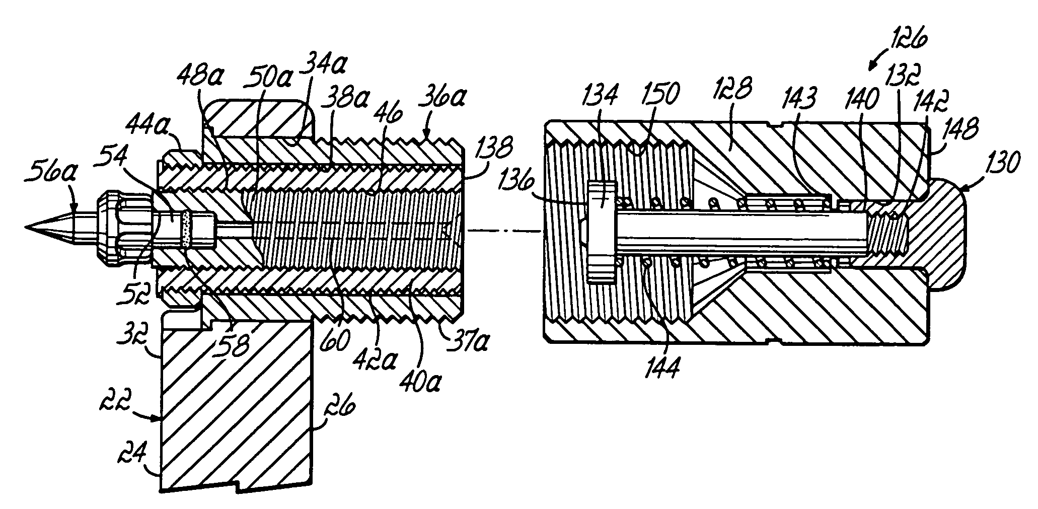
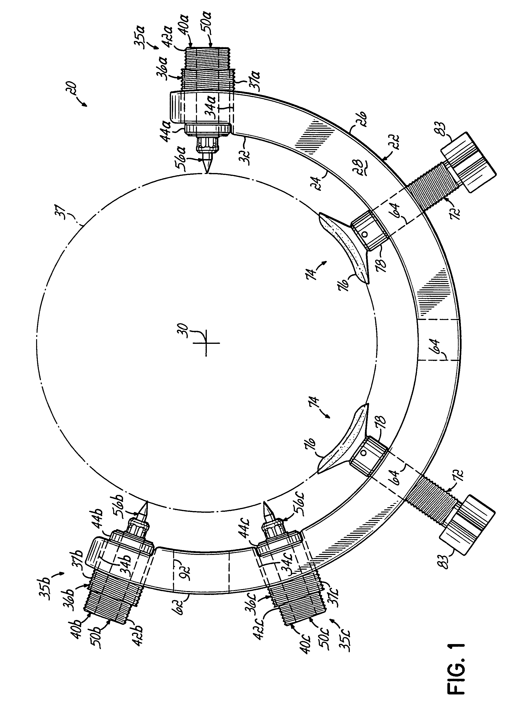
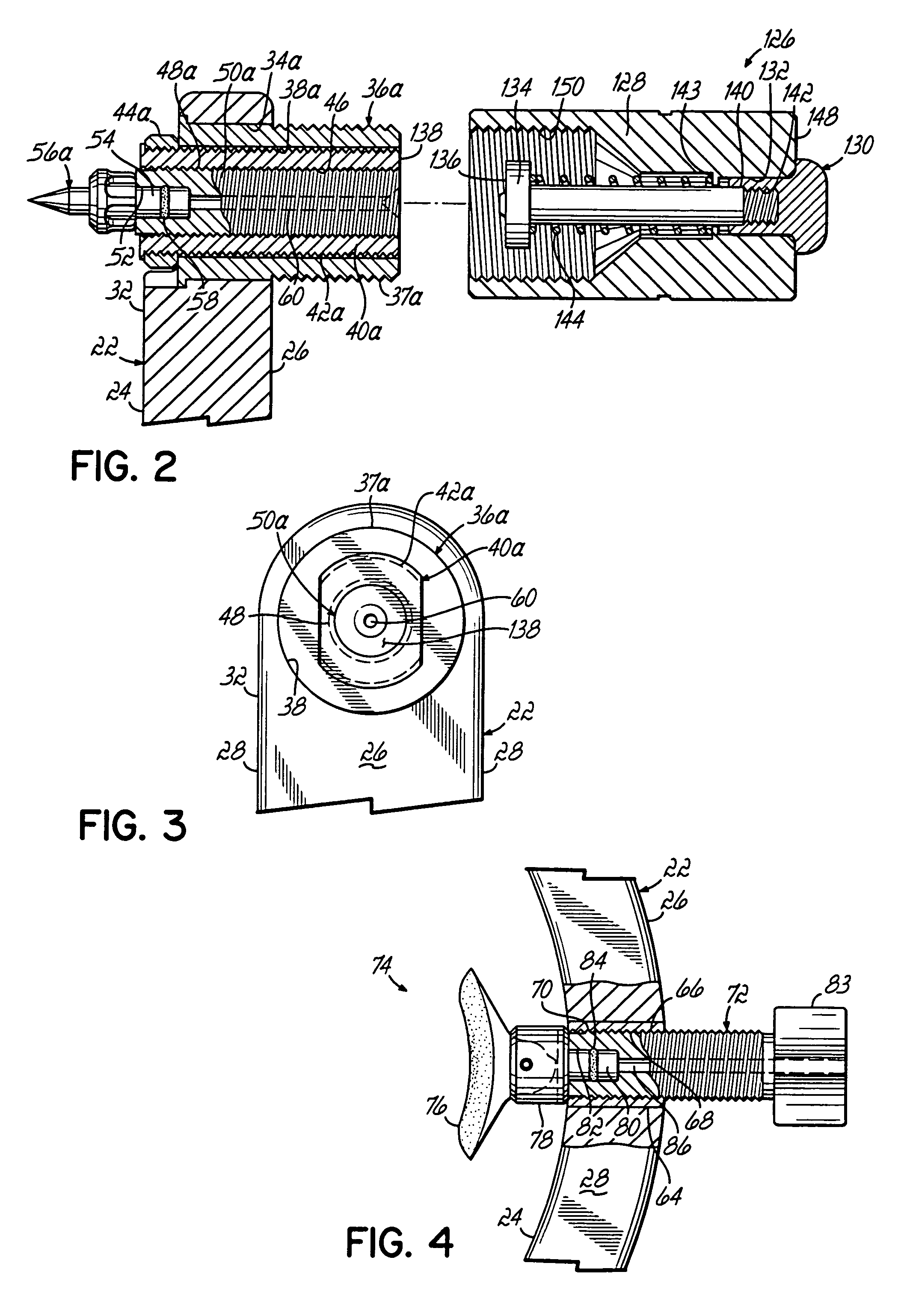
[0021]Referring to FIG. 1, a skull clamp 20 includes an arcuate, single-piece, unitary clamp body 22 that has a generally quadrilateral, for example, a rectangular, cross-sectional profile. The body 22 has an arcuate inner surface 24, an opposed arcuate outer surface 26 and opposed arcuate side surfaces 28. The body 22 is generally circular with respect to a center point 30. One end 32 of the body 22 has a generally radially directed bore 34a extending through the inner and outer surfaces 24, 26 and in which an insert 36a is rigidly mounted, for example, by an epoxy, threads or other means. A skull pin assembly 35a includes an engagement shaft 40a that is slidably mounted within the insert, and a locking nut 44a that is mounted on an inner end of the engagement shaft 40a. The skull pin assembly 35a further includes a skull pin 56a inserted in one end of a piston 50a, that, in turn, is slidably disposed within the engagement shaft 40a. The skull pin assembly 35a permits the skull pin...


PUM


Abstract

A skull pin assembly for use with a skull clamp includes a skull pin that is slidable into contact with a head of a patient. A pin load applicator is removably connectable to the skull pin assembly and includes a loading shaft that is able to apply a force against an inner end of the skull pin. The pin load applicator also has a biasing element operable to apply a force on the loading shaft that, in turn, transfers the force to the skull pin. A load force indicator is connected to the loading shaft and provides an indication of the force being applied by the skull pin. The pin load applicator permits the force being applied by the skull pin to be adjusted to a desired value; and thereafter, the pin load applicator is removed from the skull pin assembly without changing the desired skull pin force.

Description

[0001]This application claims the benefit of U.S. Provisional Application Ser. No. 60 / 446,299, filed Feb. 10, 2003.FIELD OF THE INVENTION[0002]This invention relates generally to neurosurgical apparatus and more particularly, to an improved apparatus for supporting a head of a patient.BACKGROUND OF THE INVENTION[0003]Generally, cranial stabilization refers to a line of compatible and interconnectable medical devices used during neurosurgery to hold the head of a patient in a fixed position relative to a surgical operating table. A typical arrangement of such products may include, for example, a base unit that connects directly to the surgical table, one or more adaptors connected to the base unit, and a skull clamp connected to an adaptor. The skull clamp often has three skull pins that engage and hold the skull of the patient.[0004]One type of known skull clamp is designed to accommodate all sizes of heads and is comprised of two opposed clamp arms that have proximal ends slidable ...

Claims


Application Information

Patent Timeline
Patent Type & Authority Patents(United States)
IPC IPC(8): A61B19/00
CPCA61B19/203A61B2017/00911A61B2019/465A61B90/14A61B2090/065
Inventor DINKLER, CHARLES E.
Owner INTEGRA LIFESCI
Why Eureka
Try Eureka