Systems and methods for correcting a positron emission tomography emission image

a technology of emission image and system, applied in the field of imaging systems, can solve problems such as annihilation of positrons

Inactive Publication Date: 2009-03-24
GE MEDICAL SYST GLOBAL TECH CO LLC
View PDF12 Cites 26 Cited by
  • Summary
  • Abstract
  • Description
  • Claims
  • Application Information

AI Technical Summary

Problems solved by technology

Positrons emitted by these neutron deficient compounds interact with free electr

Method used


Image

  • Systems and methods for correcting a positron emission tomography emission image
  • Systems and methods for correcting a positron emission tomography emission image
  • Systems and methods for correcting a positron emission tomography emission image

Examples


Embodiment Construction

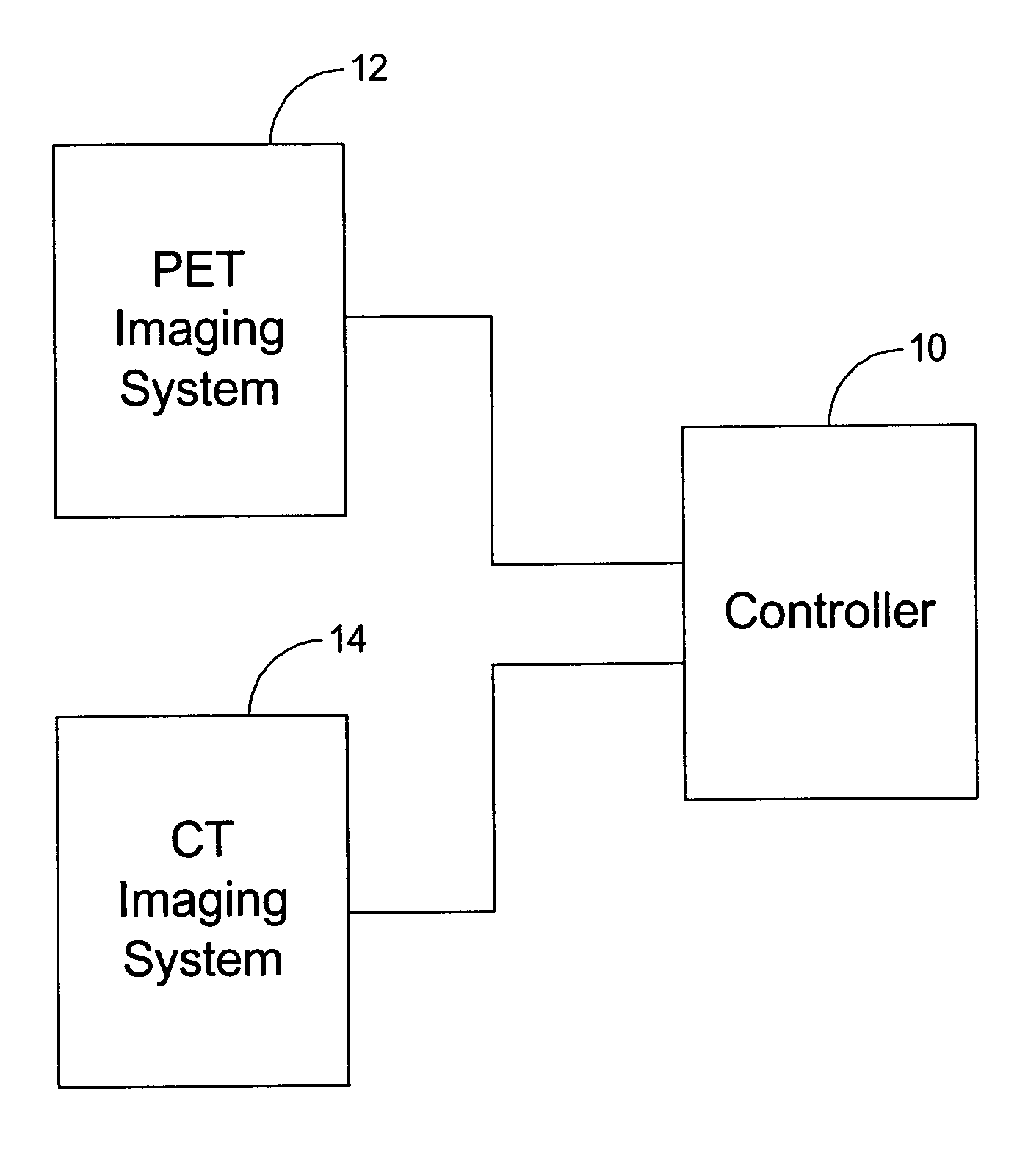
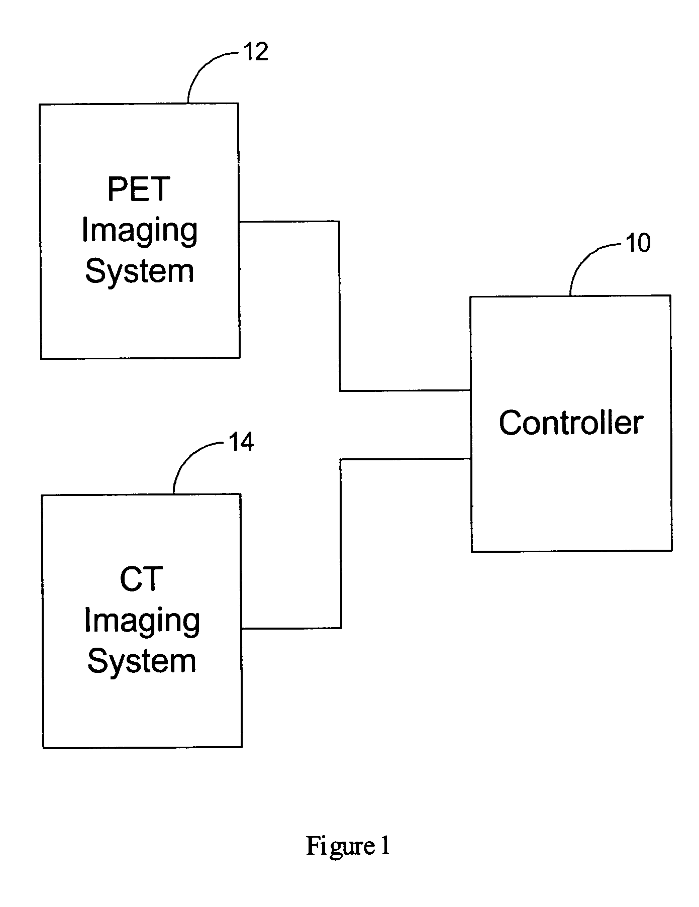
[0029]FIG. 1 is a block diagram of an embodiment of a system for correcting a positron emission tomography (PET) image. System includes a controller 10 that is electrically coupled to a PET imaging system 12 and to a computed tomography (CT) imaging system 14. The term controller is not limited to just those integrated circuits referred to in the art as computers, but broadly refers processors, microcontrollers, microcomputers, programmable logic controllers, application specific integrated circuits, and other programmable circuits.

[0030]PET imaging system 12 constructs a PET emission image from PET emission data that is generated by positrons emitted from within an object, such as a patient or a phantom. The PET emission image is transmitted from PET imaging system 12 to controller 10. CT imaging system 14 creates a CT image from CT data that is produced as a result of attenuation of x-rays passing through the object. In order to achieve maximal quantitative measurement accuracy in...


PUM


Abstract

A method for correcting a positron emission tomography (PET) emission image is described. The method includes obtaining a PET emission sinogram of an object, obtaining a computed tomography (CT) image for a scanned portion of the object, the object having a truncated portion outside a field of view (FOV) of a CT image, determining a correction set of CT data based on a measured set of CT data within the CT sinogram, generating modified attenuation correction factors from the measured and correction sets of CT data, and correcting the PET sinogram using the modified attenuation correction factors.

Description

BACKGROUND OF THE INVENTION[0001]This invention relates generally to imaging systems and more particularly to systems and methods for correcting a positron emission tomography (PET) emission image.[0002]The systems and methods are directed toward multi-modal imaging systems capable of scanning using different modalities, such as, for example, but not limited to, Positron Emission Tomography (PET) and Computed Tomography (CT). The difference between multi-mode and multi-modality is that multi-mode systems are utilized to perform scans in different modes, for example, a flouro mode and a tomosynthesis mode, while a multi-modal system is utilized to perform scans in different modalities, for example, CT and PET. It is contemplated that the benefits of systems and methods for analyzing an abnormality of an, object accrue to all multi-modal imaging systems, such as, for example, but not limited to, a PET-CT imaging system.[0003]PET has gained significant popularity in nuclear medicine be...

Claims


Application Information

Patent Timeline
IPC IPC(8): G01T1/161G01N23/00G06K9/00A61B5/00A61B5/0275A61B6/03G01T1/29G06T11/00
CPCA61B6/032A61B6/037G06T11/005G01T1/2985A61B5/02755A61B5/14532G06T2211/432A61B5/4041
Inventor WOLLENWEBER, SCOTT DAVIDGANIN, ALEXANDER
Owner GE MEDICAL SYST GLOBAL TECH CO LLC
Why Eureka
Try Eureka