
Integrated motor and resolver including absolute position capability

a technology of absolute position capability and integrated motor, which is applied in the direction of electronic commutators, program control, instruments, etc., can solve the problems of limiting the use of the motor to the smaller temperature range of the attached encoder, increasing the assembly cost of the motor, and limiting the use of the motor

Active Publication Date: 2009-03-24
QUICKSILVER CONTROLS +1
View PDF37 Cites 37 Cited by
  • Summary
  • Abstract
  • Description
  • Claims
  • Application Information

AI Technical Summary

Benefits of technology

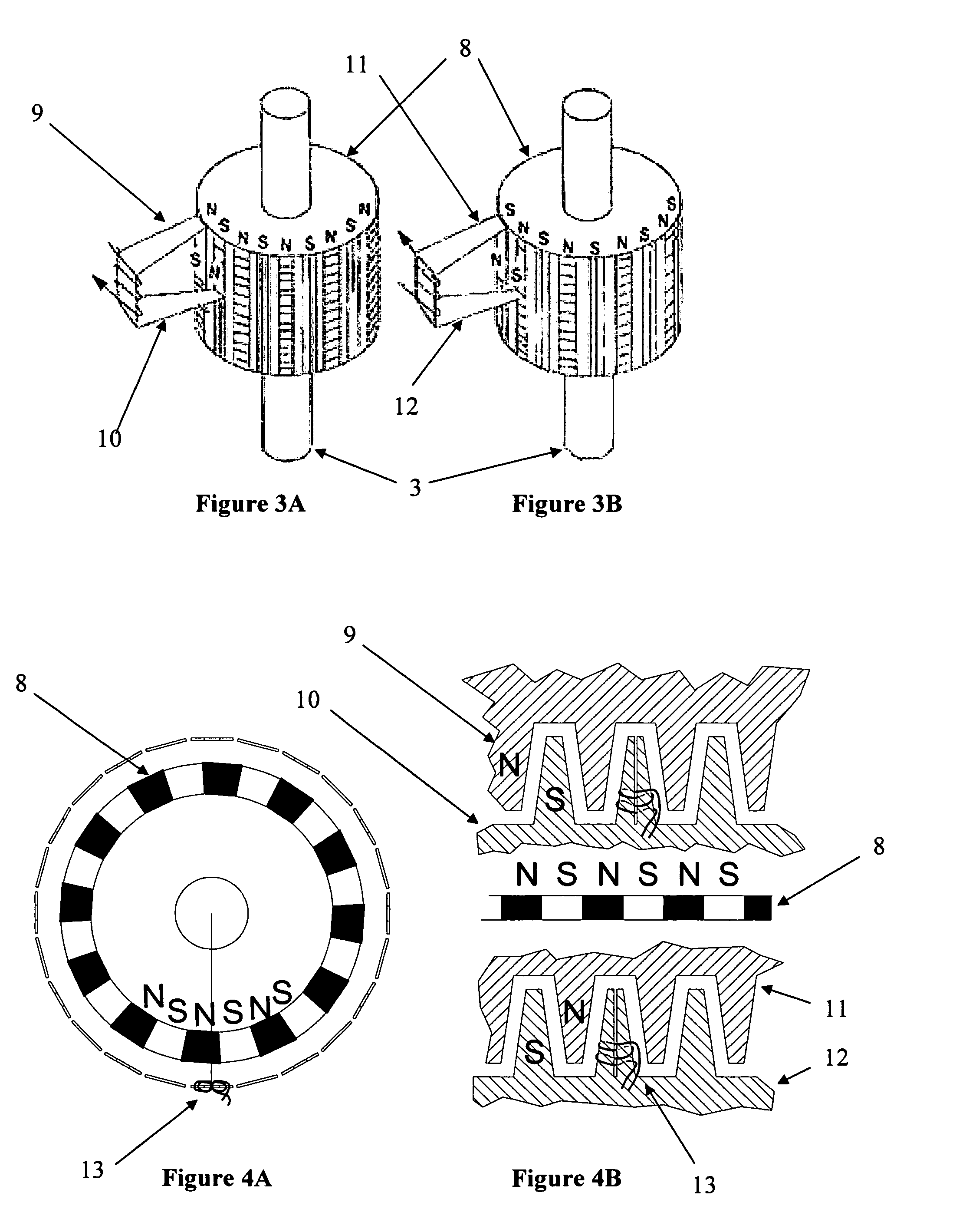
[0012]Yet another aspect of the invention provides a motor comprising first and second pole pieces on a first part of a motor. The first and second pole pieces have respective sets of teeth spaced regularly on respective faces of the first and second pole pieces. The motor includes at least one motor coil to at least in part effect motor motion between the first part of a motor and a second part of the motor when the at least one motor coil is driven. The respective sets of teeth of the first and second pole pieces magnetically interact with corresponding sets of regularly spaced teeth on the second part of the motor when the at least one motor coil is driven. First and second sensing coils are coupled to the first and second pole pieces and arranged to detect changes in magnetic flux coupling between the teeth of the first pol...

Problems solved by technology

On the other hand, encoders can be expensive in that an encoder can be a major portion of the cost of a motor.
Encoders require alignment and additional wiring and can add significantly to the assembly costs of a motor.
Encoders also typically have a reliable temperature range that is smaller than the temperature range of the motor to which they are attached, limiting the use of the motor to the smaller temperature range of the attached encoder.
This can limit the power that can be practically achieved with the system due to the reduced temperature range.
When a resolver is implemented as an add on to an existing motor structure, it increases the cost of the components of the motor and also increases the assembly costs for the motor.

Method used


Image

  • Integrated motor and resolver including absolute position capability
  • Integrated motor and resolver including absolute position capability
  • Integrated motor and resolver including absolute position capability

Examples


Embodiment Construction

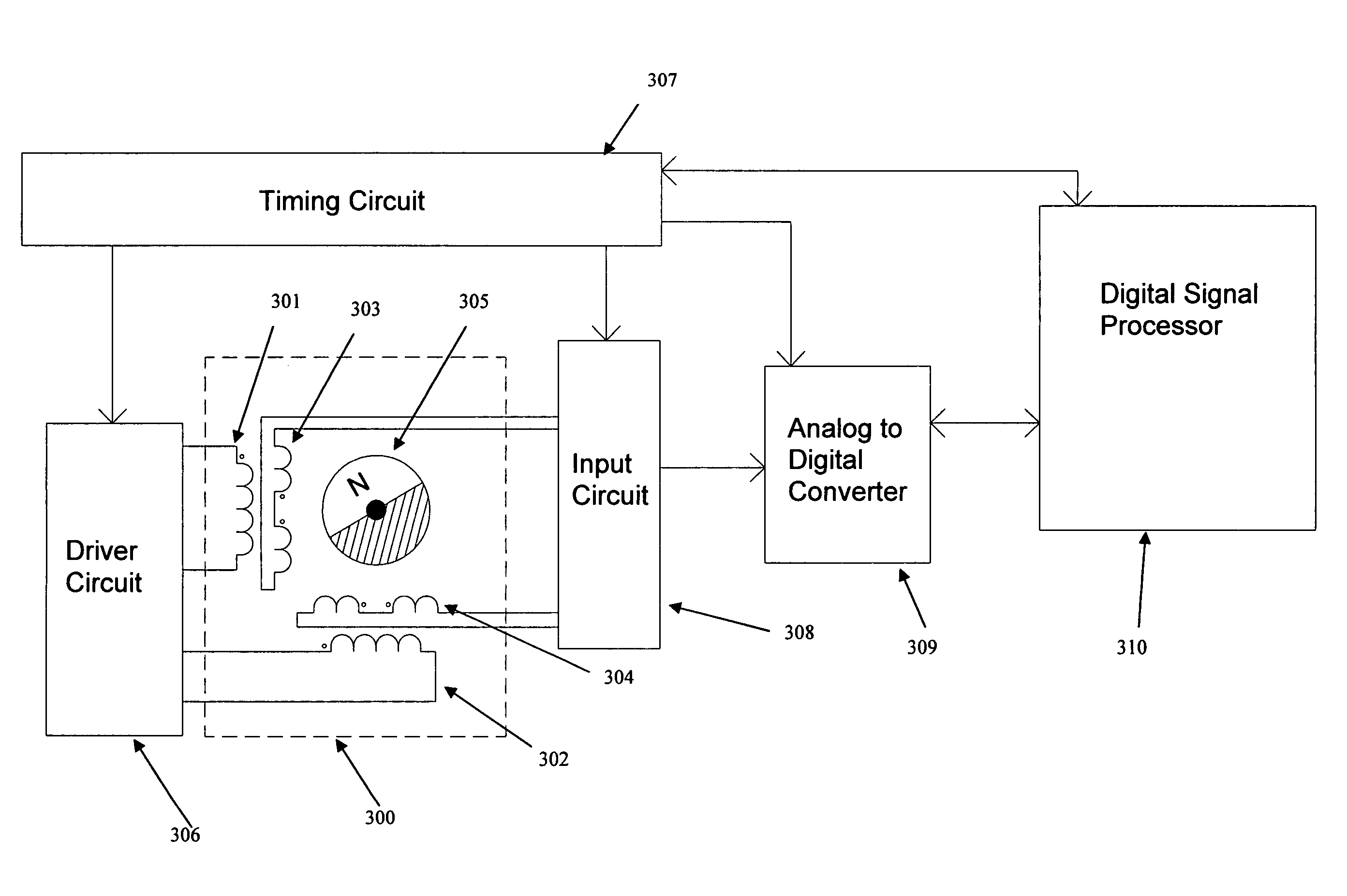
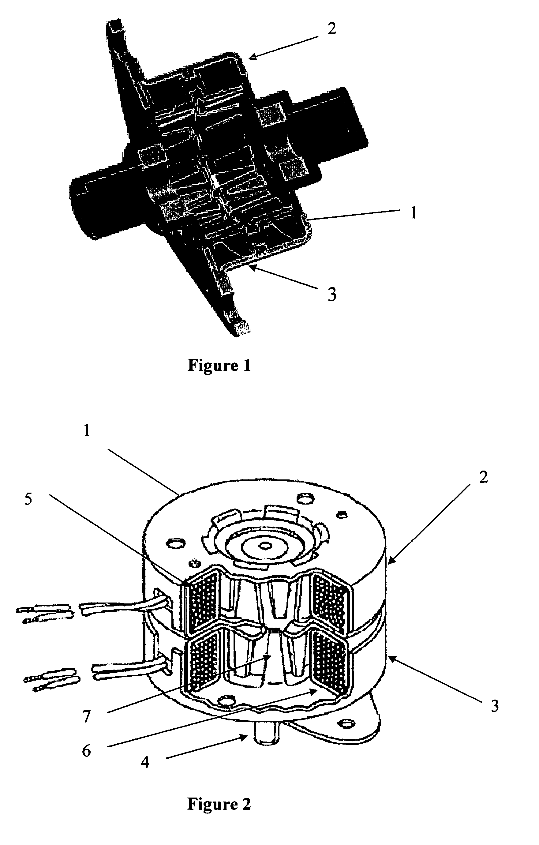
[0009]An aspect of the invention provides an integrated motor and position sensor comprising a motor comprising a rotor assembly including a cylindrical portion having an axis. The cylindrical portion of the rotor assembly has a plurality of peripherally-spaced and alternately magnetized regions. The motor further comprises a stator assembly coaxial with the rotor assembly and having a plurality of stator poles projecting toward the rotor assembly, arranged substantially coaxial with the rotor assembly. The motor also comprises coils for electrically energizing the stator poles. The integrated motor and position sensor in turn comprises a plurality of sensing coils placed to intercept the magnetic flux between a plurality of the stator poles and the rotor assembly.

[0010]Another aspect of the invention provides an integrated motor and position sensor comprising a motor comprising a rotor assembly and a stator assembly. The rotor assembly includes a cylindrical portion having an axis ...


PUM


Abstract

An integrated motor and position sensor achieves motion between a moving portion and a stationary portion by electrically energizing poles to interact with magnetics respectively on the moving and stationary portions. The position sensor includes a plurality of sensing coils placed to intercept the magnetic flux between a plurality of the poles and the magnetics. The outputs from these coils are fed to a microprocessor or DSP through an internal or external A / D converter. The microprocessor or DSP decodes the measured voltages using resolver strategies to produce a position, velocity or acceleration measurement.

Description

BACKGROUND[0001]1. Field of the Invention[0002]This invention relates to a motor having a resolver for detecting a position, velocity or acceleration that is determined by the motor and, in a specific application, to such a motor associated with a control system that uses the position, velocity or acceleration in controlling the motor.[0003]2. Description of the Related Art[0004]Motors are used in a variety of applications for effecting the controlled motion of objects. For example, motors are used in a variety of industrial automation and other automation applications. In many applications, it is useful to provide the motor or the motor's controller with an accurate measure of the motor position to allow for greater precision in positioning objects with the motor. In other applications, it is useful to provide the motor or its controller with an accurate measure of the velocity or acceleration of the motor's rotor. Position, velocity and acceleration information can be useful howev...

Claims


Application Information

Patent Timeline
IPC IPC(8): G05B19/29
CPCH02K11/0031H02K41/03H02P6/165H02K37/14H02K37/18H02K11/225H02P6/17
Inventor LABRIOLA, II, DONALD P.
Owner QUICKSILVER CONTROLS
Learn More