Exterior component disposed on front surface of radar device of vehicle

a radar device and exterior component technology, applied in the direction of antennas, antenna details, antenna adaptation in movable bodies, etc., to achieve the effect of improving the aesthetic appearance of the exterior vehicle component and low cos

Inactive Publication Date: 2009-03-24
HONDA MOTOR CO LTD
View PDF10 Cites 21 Cited by
  • Summary
  • Abstract
  • Description
  • Claims
  • Application Information

AI Technical Summary

Benefits of technology

[0011]With the above-described structural configuration of the first feature, the proximity member is disposed outside of the electromagnetic wave transmission member in a radial direction thereof and is transmissible of the electromagnetic wave in the exterior vehicle component. The proximity member has a portion formed on a front surface thereof by depositing a surface treatment therein so as to reflect an electromagnetic wave. The proximity member is formed of a material having an attenuation coefficient for electromagnetic wave transmission that is equal to or greater than a predetermined value. Therefore, even if the electromagnetic wave transmitted from the radar device mounted on the vehicle passes through the proximity member, the wave is reflected by the surface treatment and is received by the radar device. Thus, the intensity of the electromagnetic wave is suppressed to a low enough value so as to prevent influencing the detection accuracy. Thus, it is unnecessary to use a deposit of expensive indium thereon which does not reflect the electromagnetic wave for the surface treatment of the proximity member. This can contribute to an increase in degree of freedom of the design and a reduction in the cost of the exterior vehicle component.
[0025]With the arrangement of the eighth feature, the exterior vehicle component is an emblem provided on the front grill, thereby decorating the front grill with the emblem without impairing the function of the radar device.

Problems solved by technology

Thus, it is unnecessary to use a deposit of expensive indium thereon which does not reflect the electromagnetic wave for the surface treatment of the proximity member.

Method used


Image

  • Exterior component disposed on front surface of radar device of vehicle
  • Exterior component disposed on front surface of radar device of vehicle
  • Exterior component disposed on front surface of radar device of vehicle

Examples


Embodiment Construction

[0031]The present invention will now be described by way of embodiments with reference to the accompanying drawings.

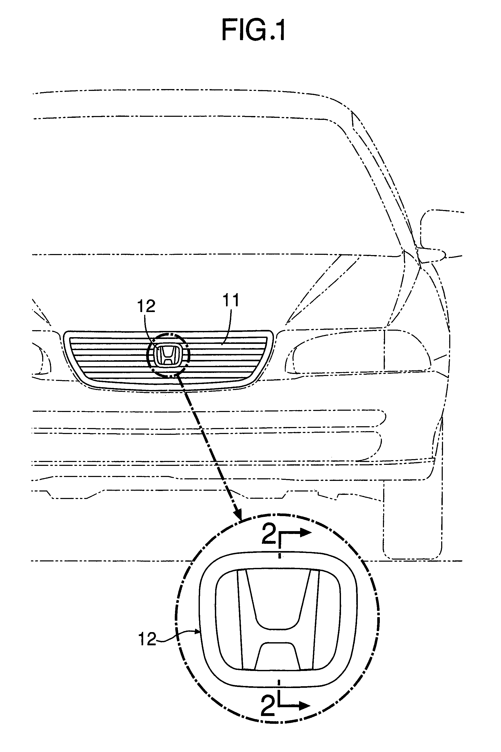
[0032]As shown in FIG. 1, an emblem 12 for enhancing a design effect is mounted at a central portion of a front grill 11 of an automobile.

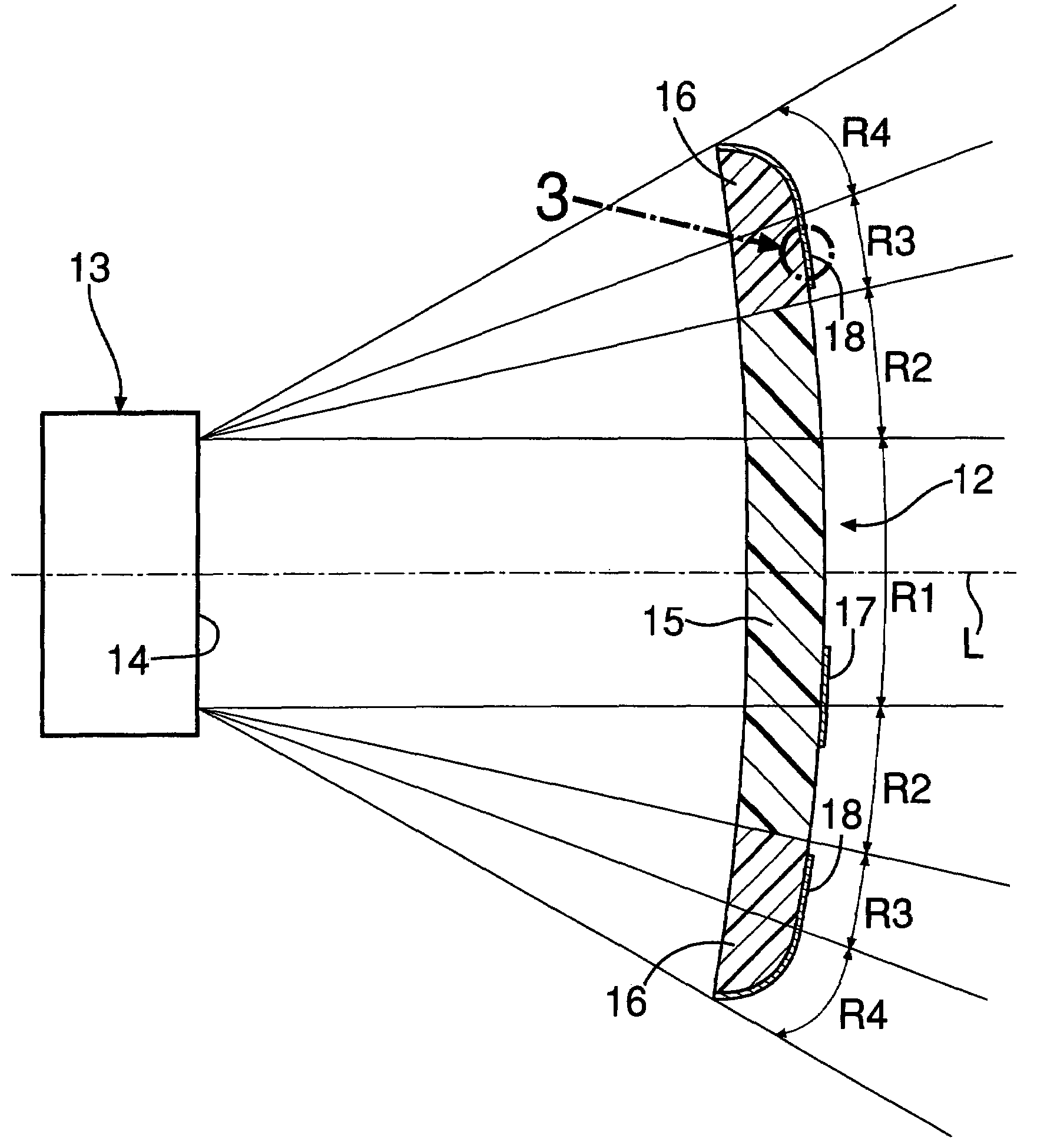
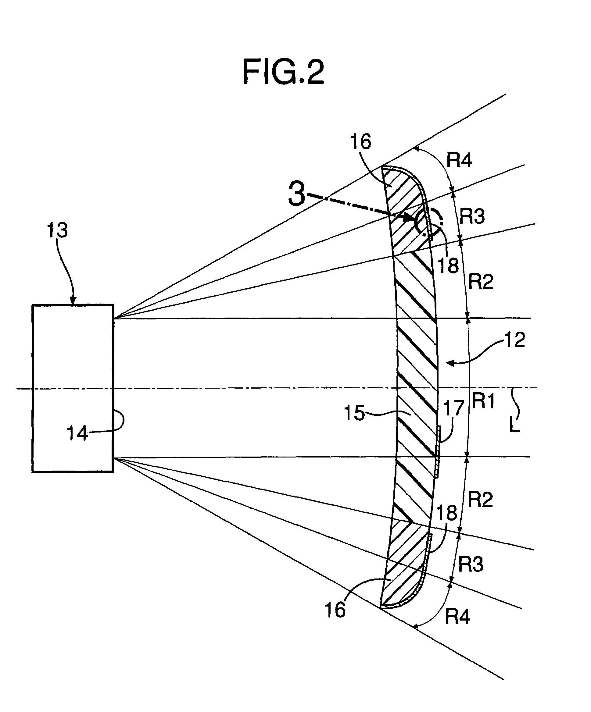
[0033]FIG. 2 is a cross-sectional view of the emblem 12. A radar device 13 disposed behind the emblem 12 relative to a forward end of the subject automobile (or vehicle) is adapted to transmit an electromagnetic wave (millimeter wave) forward along an axis L from an antenna opening 14 provided in a front surface of the radar device 13. Also, the radar device 13 is adapted to receive the wave reflected from a detected object, thereby detecting a distance, a direction and relative speed of the obstacle, such as, for example, a vehicle located ahead of the subject vehicle.

[0034]The emblem 12 may have any suitable geometric shape. For example, the illustrated embodiment of the emblem12 is a substantially quadrilateral plate-shape. The em...


PUM


Abstract

An exterior vehicle component includes a proximity member disposed along an outer perimeter of an electromagnetic wave transmission member provided at a center of the component which is disposed in front of a radar device. The proximity member includes a chromium-plated portion formed on its front surface which reflects an electromagnetic wave. The proximity member is formed of an acrylate-styrene-acrylonitrile resin or a modified polyphenylene oxide resin having an attenuation coefficient for electromagnetic wave transmission, which is equal to or greater than a predetermined value.

Description

RELATED APPLICATION DATA[0001]The present invention is based upon Japanese priority application No. 2006-063973, which is hereby incorporated in its entirety herein by reference.BACKGROUND OF THE INVENTION[0002]1. Field of the Invention[0003]The present invention relates to an exterior component disposed on a front surface of a radar device of a vehicle and in an electromagnetic wave transmitting and receiving path in front of the radar device mounted on the vehicle.[0004]2. Description of the Related Art[0005]The front grill of an automobile, which is made of resin, usually has a chromium-plated surface which enhances the design's metallic appearance. When a radar device mounted in the rear section of the front grill is used for detecting an obstacle, such as, for example, a vehicle located in front of or ahead of the subject vehicle, an electromagnetic wave transmitted and received by the radar device is reflected from a chromium-plated layer on a front section of the front grill,...

Claims


Application Information

Patent Timeline
Patent Type & Authority Patents(United States)
IPC IPC(8): H01Q15/02
CPCH01Q1/3233H01Q17/001H01Q19/10G01S7/03G01S2013/93271
Inventor SHINGYOJI, MASAHITO
Owner HONDA MOTOR CO LTD
Why Eureka
Try Eureka