Systems and methods for monitoring and tracking movement and location of shipping containers and vehicles using a vision based system

a technology of vision based system and tracking system, applied in the field of tracking the location of shipping objects, can solve the problems of manual system that employs manual identification and recordation of shipping container location, manual system that does not provide real-time reporting of container location, and manual system that does not provide automatic reporting, so as to achieve the effect of low cost and minimal error ra

Active Publication Date: 2009-03-24
ABB INC
View PDF19 Cites 23 Cited by
  • Summary
  • Abstract
  • Description
  • Claims
  • Application Information

AI Technical Summary

Benefits of technology

[0016]The present invention provides for systems and methods for tracking and locating shipping objects, such as containers, chassis and vehicles at transit terminals using an automated vision-based tracking system. The transit terminal may be an automotive terminal, a marine vessel terminal, a rail terminal an intermodal terminal or any other transit terminal. Such a system is ideally suited to provide minimal error rates, low cost implementation, real-time data and automatic merging of data with corresponding container identification systems and terminal operating systems. The systems and methods of the present invention provide for location-tracking of containers without the need to retrofit containers with a tagging or marker device. The vision-based system incorporates the use of multiple imaging devices and a hand-off method for tracking the location of the containers over extended distances.
[0018]The typically system will incorporate an array of imaging devices disposed at various predetermined locations within the terminal yard and corresponding to a position on an overall imaging device grid array. The vision-based system is capable of handing-off the tracking task from one computer to another as the vehicle or container moves from one imaging device's field of view to another imaging device's field of view. The vision / tracking system “watches” or detects the container as the container moves thru the entry OCR gate and obtains the OCR identification information from the OCR system. This identifying information is then used by the vision-based tracking system to identify the container as it is moved about the terminal yard. Additional OCR input points can include stations associated with container handling equipment, such as top picks, side picks, transfer crane, quay cranes and the like. The vision-based tracking system provides the capability to detect which pedestal that a vehicle and / or container comes in contact with, after passing thru the initial OCR entry gate.
[0032]As such the present invention provides for systems and methods for location-identification and monitoring of objects, such as shipping containers, at a transit terminal using an automated vision based tracking system. The transit terminal may be an automotive terminal, a marine terminal, a rail terminal an intermodal terminal or the like. Such a system is ideally suited to provide minimal error rates, low cost implementation, real-time data and automatic merging of data with corresponding object identification systems and terminal operating systems. The systems and methods of the present invention provide for location-tracking of objects without the need to retrofit the objects with a tagging or marker device. The vision-based system incorporates the use of multiple imaging devices and a hand-off method for tracking the location of the objects over extended distances.

Problems solved by technology

As is the case with any process that involves manual input of data, a system that employs manual identification and recordation of shipping container location is plagued with errors.
Additionally, the manual systems do not provide for real-time reporting of container location nor do they provide for automated direct entry of container location into the terminal's computerized operating system, referred to herein as the Terminal Operating System (TOS).
However, both of these types of systems are problematic.
Invariably, such a system will be prone to fail because not all containers would be augmented with the RF tag and, as such, containers would enter the terminal that would be unidentifiable.
In the same regard, the cost related to tagging each container makes such a system cost prohibitive.
Additionally, since typical shipping terminals employ a high degree of ground level metal, (acting as a radio signal reflector), long or medium range RF identification becomes very problematic.
In addition to the problem of providing real-time location-identification for shipping containers at the terminal, current systems provide no automatic means to identify the container location on a vessel.
Therefore, it is difficult to get a fix on the vessel's grid.
While modem quay cranes used to load and unload vessels have a means for “knowing” or locating a container within their own frame of reference, it is difficult to match up the crane's frame of reference with the vessel's frame of reference.
In most instances, unauthorized vehicles or personnel in the landing zone will trigger an alarm-notification or auto-shutdown of the quay crane operation.
In addition to locating containers on shipping vessels, another problem exists with triggering crane-mounted OCR systems, which are used to identify containers as they are placed on and removed from shipping vessels.
While some crane controllers have a means for providing the requisite positional data, other crane controllers are not equipped to provide this data.
Even in the instance in which the crane controller is equipped to provide the positional data, many of the controllers do not readily allow for outside connection to the system or access to the data is cost-prohibitive.
In addition, in many instances crane system warranties are invalidated if additional foreign equipment or devices are added to the crane system.
In certain other embodiments the controller is not readily equipped with a means for external data connection.

Method used


Image

  • Systems and methods for monitoring and tracking movement and location of shipping containers and vehicles using a vision based system
  • Systems and methods for monitoring and tracking movement and location of shipping containers and vehicles using a vision based system
  • Systems and methods for monitoring and tracking movement and location of shipping containers and vehicles using a vision based system

Examples


Embodiment Construction

[0052]The present inventions now will be described more fully hereinafter with reference to the accompanying drawings, in which some, but not all embodiments of the invention are shown. Indeed, these inventions may be embodied in many different forms and should not be construed as limited to the embodiments set forth herein; rather, these embodiments are provided so that this disclosure will satisfy applicable legal requirements. Like numbers refer to like elements throughout.

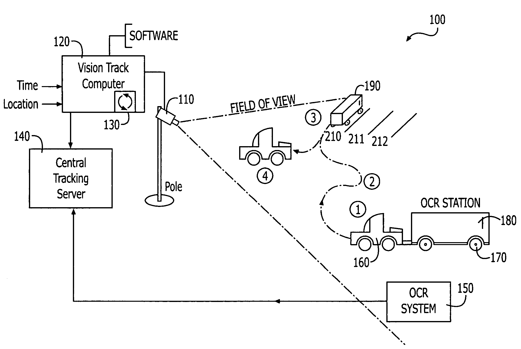
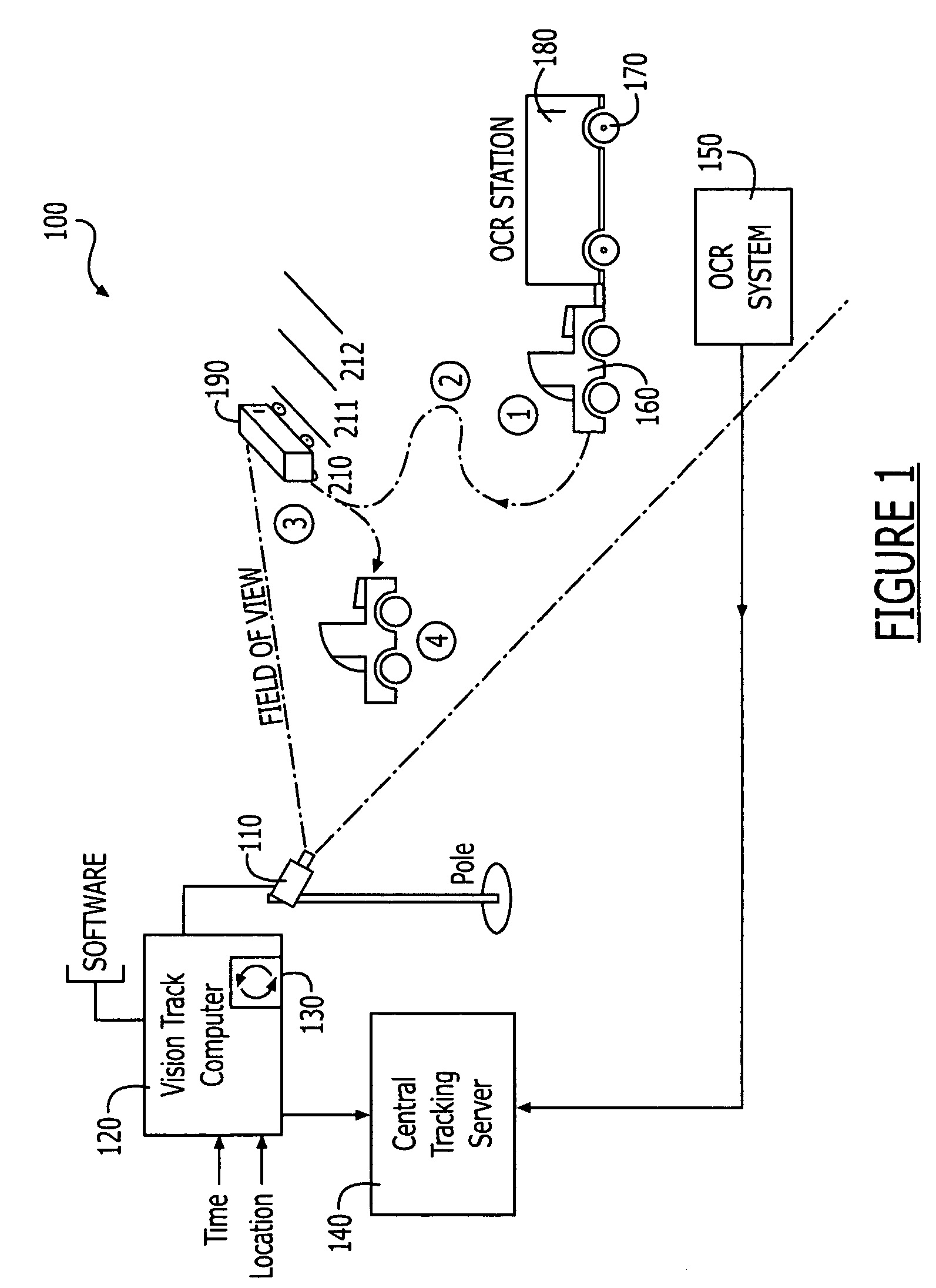
[0053]FIG. 1 illustrates a schematic diagram of a system for vision-based, location-tracking of movable objects, such as vehicles, containers and / or chassis in a transit terminal environment, in accordance with an embodiment of the present invention. The transit terminal may be an automotive terminal, a marine vessel terminal, a rail terminal, an intermodal terminal or any other transit terminal. The vision-based, location-tracking system 100 includes one or more, imaging devices 110 typically positioned at pre...


PUM


Abstract

The invention provides for systems and methods for location-identification and monitoring of objects, such as shipping containers, at a transit terminal using an automated vision based tracking system. Such a system is ideally suited to provide minimal error rates, low cost implementation, real-time data and automatic merging of data with corresponding object identification systems and terminal operating systems. The systems and methods of the present invention provide for location-tracking of objects without the need to retrofit the objects with a tagging or marker device. The vision-based system incorporates the use of multiple imaging devices and a hand-off method for tracking the location of the objects over extended distances.

Description

CROSS-REFERENCE TO RELATED APPLICATIONS[0001]This application claims the benefit of U.S. Provisional Application No. 60 / 475,810, filed Jun. 4, 2003.FIELD OF THE INVENTION[0002]The present invention relates to tracking location of shipping objects, and more particularly to systems and methods for real time monitoring of the location of shipping objects at or about transit terminal using a vision based tracking system.BACKGROUND OF THE INVENTION[0003]The ability to track and locate shipping containers within a terminal, such as a marine, rail or intermodal terminal, is critical to the operation of the terminal. When containers are brought into a marine container terminal on a truck chassis, they are typically parked in a parking spot prior to being loaded on a ship / vessel for transport. The ability to find and load or move the correct container depends on knowing, in real-time, where the container has been parked, i.e., real-time knowledge of where the container is located within the ...

Claims


Application Information

Patent Timeline
Patent Type & Authority Patents(United States)
IPC IPC(8): G06K9/00G06F19/00G06T7/20
CPCG06K9/00785G06Q10/08G06T7/2093G06T2207/30232G06T7/292G06V20/54
Inventor SCHEPPMANN, LEROY E.
Owner ABB INC
Why Eureka
Try Eureka