Liquid detecting device, liquid container, and liquid refilling method

a liquid detecting device and liquid container technology, applied in liquid/fluent solid measurement, instruments, machines/engines, etc., can solve the problem of large attenuation of the remaining vibration waveform

Inactive Publication Date: 2009-03-31
SEIKO EPSON CORP
View PDF10 Cites 1 Cited by
  • Summary
  • Abstract
  • Description
  • Claims
  • Application Information

AI Technical Summary

Benefits of technology

[0009]According to the aspect of the invention, a part of the movable member biased by the biasing member is attached to the flexible diaphragm. When the liquid pressure in the liquid detection chamber increases, the diaphragm expands to thereby increase the volume of the liquid detection chamber. As a result, the pressure receiving plate becomes spaced apart from the one surface of the detection-portion-mounted member against the biasing force of the biasing member. When the ink pressure becomes smaller than a predetermined value, the movable member is displaced by the biasing force of the biasing member. As a result, the pressure receiving plate is brought into contact with the one surface of the detection-portion-mounted member and the diaphragm is displaced to the position where the volume of the liquid detection chamber decreases. When the pressure receiving plate is spaced apart from the detection-portion-mounted member such that the detection space portion is opened to the ink detection chamber, attenuation of a remaining vibration waveform is small. On the other hand, when the pressure receiving plate is brought into contact with the detection-portion-mounted member such that the detection space portion is blocked, attenuation of the remaining vibration waveform is large. Through the difference described above, liquid detection, such as the amount of remaining liquid and the pressure of liquid, based on the position of the movable member becomes possible.
[0013]In the liquid detecting device according to the aspect of the invention, the movable member may include: an upstream-side member which is formed to extend from the pressure receiving plate toward the liquid inlet along the first direction of the two perpendicular axes; and a downstream-side member which is formed to extend from the pressure receiving plate toward the liquid outlet along the first direction of the two perpendicular axes. The first passage may be formed in the upstream-side member and the pressure receiving plate and may guide the liquid to the detection space portion through one through hole formed from the liquid inlet to the detection-portion-mounted member. In addition, the second passage may be formed in the downstream-side member and the pressure receiving plate and may guide the liquid to the liquid outlet through the other through hole formed from the detection space portion to the detection-portion-mounted member. In this manner, liquid can be reliably filled into the detection space portion at the initial stage when liquid is introduced into the liquid detection chamber due to a capillary phenomenon or an attraction effect in the first and second passages.
[0015]By sealing the second passage of the downstream-side member of the movable member portion at the initial stage when liquid is introduced into the liquid detection chamber, the liquid can be reliably filled into the detection space portion due to the capillary phenomenon or the attraction effect in the first and second passages. In addition, it is possible to discharge bubbles generated in the detection space portion and to realize highly precise liquid detection by preventing the detection accuracy from deteriorating due to existence of bubbles.
[0017]In this case, since the mounting accuracy of the pressure receiving plate and the detection-portion-mounted member with respect to the liquid detection chamber is improved, the reliability in which the detection space portion can be filled with liquid at an initial stage when liquid is introduced into the liquid detection chamber is improved.
[0019]By setting up the distance between the two standing members as described above, it is possible to improve the positional accuracy of the pressure receiving plate if needed when the pressure receiving plate comes in contact with the detection-portion-mounted member.
[0020]In the liquid detecting device according to the aspect of the invention, the front end surface of each of the two shafts may be curved. In this case, since the frictional resistance to the facing member is reduced, the movable member can move smoothly.

Problems solved by technology

On the other hand, when the pressure receiving plate is brought into contact with the detection-portion-mounted member such that the detection space portion is blocked, attenuation of the remaining vibration waveform is large.

Method used


Image

  • Liquid detecting device, liquid container, and liquid refilling method
  • Liquid detecting device, liquid container, and liquid refilling method
  • Liquid detecting device, liquid container, and liquid refilling method

Examples


Embodiment Construction

[0041]Hereinafter, an exemplary embodiment of the invention will be described. In addition, the present embodiment to be described below does not unduly limit the contents of the invention as defined in the appended claims, and all constituent elements described in the present embodiment are not necessarily indispensable as a solving means of the invention.

[0042](Outline of a Liquid Ejecting Apparatus)

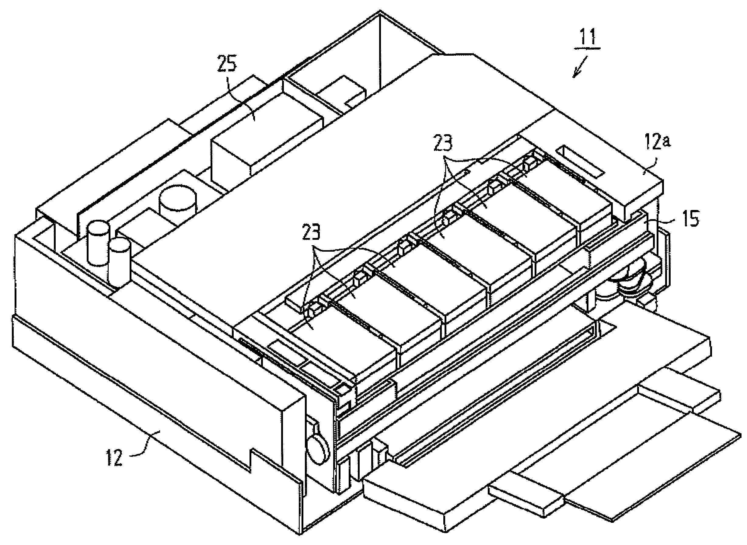
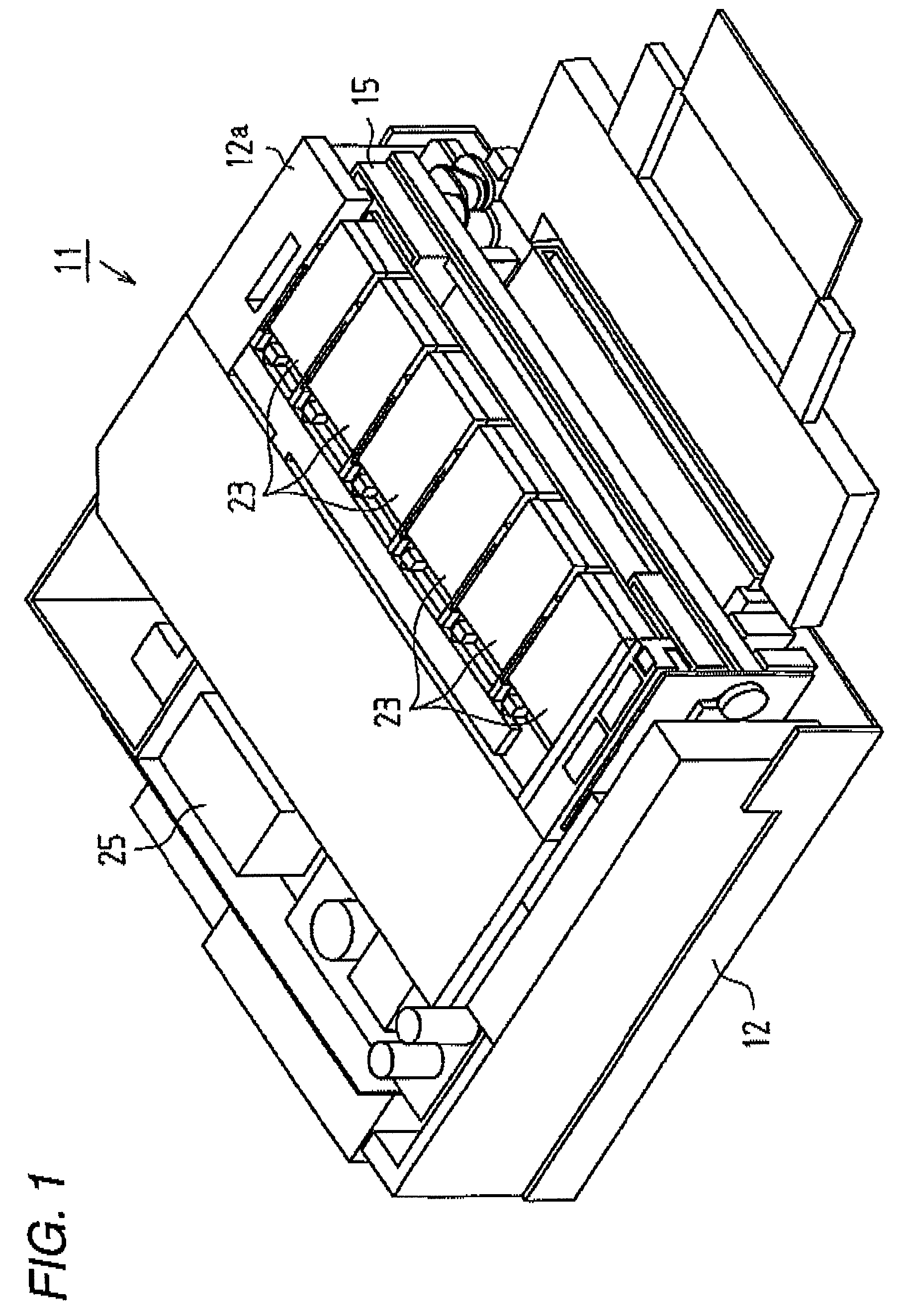
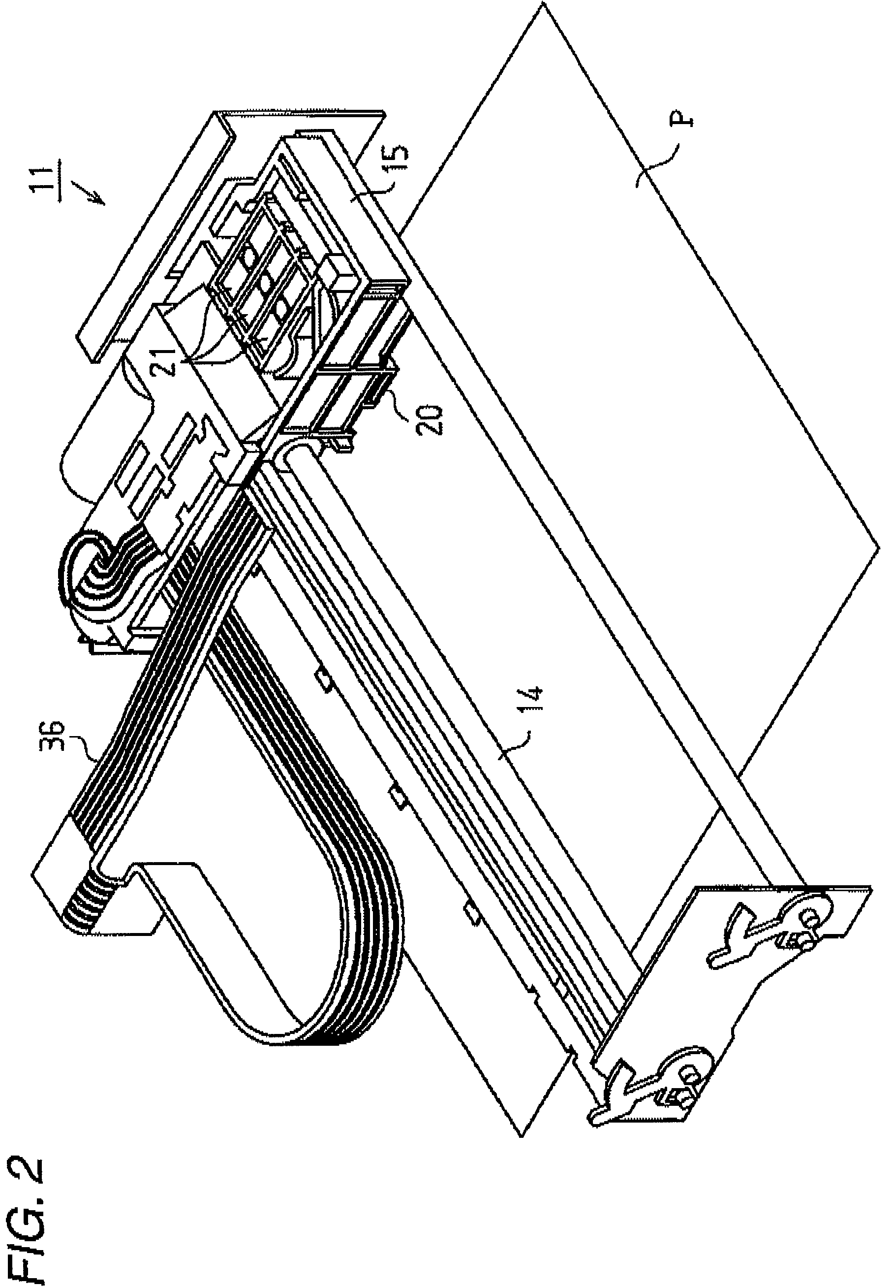
[0043]As shown in FIG. 1, a printer 11 as a liquid ejecting apparatus according to the present embodiment is covered with a frame 12. In addition, as shown in FIG. 2, a guide shaft 14, a carriage 15, a recording head 20 serving as a liquid ejecting head, a valve unit 21, an ink cartridge 23 (refer to FIG. 1) serving as a liquid containing body, and a pressure pump 25 (refer to FIG. 1) are provided inside the frame 12.

[0044]As shown in FIG. 1, the frame 12 is a housing having an approximately rectangular parallelepiped shape, and a cartridge holder 12a is formed on a front surface.

[0045...


PUM


Abstract

A liquid container includes; a liquid containing portion for containing liquid therein; a unit case, including a liquid inlet communicating with the liquid containing portion, a liquid outlet for supplying the liquid outside, a flexible diaphragm that covers an upper opening of the unit case and that is displaceable depending on liquid pressure between the liquid inlet and the liquid outlet; a movable member attached to the flexible diaphragm and that has a pair of shafts formed to protrude from opposite sides of the movable member; a sensor assembly attached to a bottom opening formed in a bottom plate of the unit case and used for detecting that the liquid in the liquid containing portion is exhausted to a predetermined amount; and a pair of shaft receiving portions that is provided on the unit case for receiving the pair of the shafts to fix the movable member in a predetermined position in an initial state where the liquid has not flowed from the liquid inlet to the detection portion.

Description

BACKGROUND[0001]1. Technical Field[0002]The present invention relates to a liquid detecting device, a liquid container, and a liquid refilling method suitable for detecting the amount of remaining ink in an ink cartridge.[0003]2. Related Art[0004]A technique of detecting the amount of remaining liquid in an ink cartridge or the like by using a piezoelectric detecting means is known (refer to Patent Document 1). In this technique, a sensor chip which constitutes a piezoelectric detecting means has a sensor cavity and an electrical property of the piezoelectric detecting means changes depending on existence of liquid in the sensor cavity, thereby detecting an ink end or an ink near end.[0005]Patent Document 1: JP-A-2006-160371 (0056-0057, 0076)[0006]Unlike the technique disclosed in Patent Document 1, in order to perform detection of an ink end and an ink near end in a condition where liquid is filled in the sensor cavity all the time, erroneous detection occurs if ink is not reliably...

Claims


Application Information

Patent Timeline
Patent Type & Authority Patents(United States)
IPC IPC(8): B41J2/175
CPCB41J2/175B41J2/17509B41J2/17513B41J2/17553B41J2/17566
Inventor AOKI, YUJIKIMURA, HITOTOSHI
Owner SEIKO EPSON CORP
Why Eureka
Try Eureka