Variable flow rate valve and method of reducing wear on same

a variable flow rate, valve technology, applied in the direction of functional valve types, fuel injecting pumps, machines/engines, etc., can solve the problems of variable flow rate valve members slanting, or even bouncing, and causing wear on so as to reduce the wear of the variable flow rate valve member and slow the advancement rate of the intensifier piston

Active Publication Date: 2009-03-31
CATERPILLAR INC
View PDF6 Cites 10 Cited by
  • Summary
  • Abstract
  • Description
  • Claims
  • Application Information

AI Technical Summary

Benefits of technology

[0011]In yet another aspect of the present invention, there is a method of operating a fuel injector. In order to slow an advancement rate of an intensifier piston over a portion of the intensifier piston advancement, a flow area of a rate shaping path is restricted by a variable flow rate valve relative to a flow area of an unrestricted intensifier path. During the intensifier piston retraction, the flow area of the rate shaping path is unrestricted by the variable flow rate valve relative to the flow area of the rate shaping path during the intensifier piston advancement. By guiding the variable flow rate valve member along guide bore walls within the rate shaping path, the variable flow rate valve wear is reduced.

Problems solved by technology

Engineers have discovered that the flow control valve member may not always rest against the flat valve seat when the actuation fluid is not acting on the closing hydraulic surface.
The repeated impacts between the valve member and the valve surface can cause the valve member and / or valve seat to wear, which can eventually cause the valve to be unable to fully close when seated.
Further, the hydraulic pressure of the actuation fluid acting on the closing hydraulic surface can be uneven, causing the variable flow rate valve member to slant, or even bounce, within the guide bore of the rate shaping path.
Moreover, the actuation fluid flowing through the passages of the slanted variable flow rate valve member can create wear on the variable flow rate valve member.
In addition to valve member wear caused by the hydraulic pressure acting on the closing hydraulic surface, wear may be caused to the edges of the valve member by actuation fluid flow around the valve member.
The change in the shape of the flow area defined by the valve member over time may also cause a change in the injector performance over time.
Moreover, engineers have found that cavitation within the passages through and around the variable flow rate valve member can also cause wear on the variable flow rate valve member and / or valve seat.
Again, the wear on the variable flow rate valve member can alter the flow area around and through the variable flow rate valve member, which in return alters the rate shape and quantity of the injection.
Thus, due to variable flow rate valve wear, the ability to control injection variables with consistency and predictability is reduced, and emission reductions can be adversely affected.

Method used


Image

  • Variable flow rate valve and method of reducing wear on same
  • Variable flow rate valve and method of reducing wear on same
  • Variable flow rate valve and method of reducing wear on same

Examples


Embodiment Construction

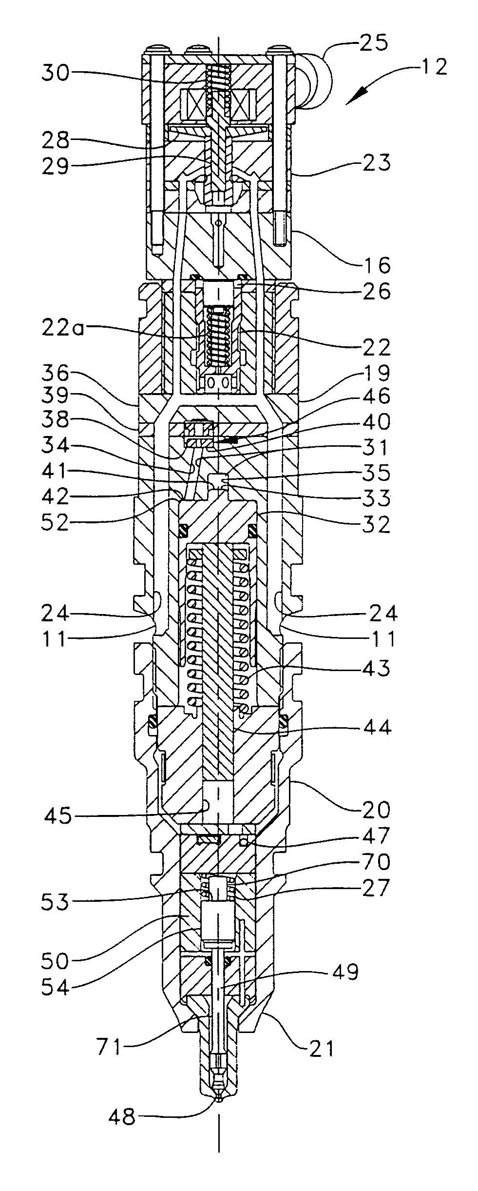
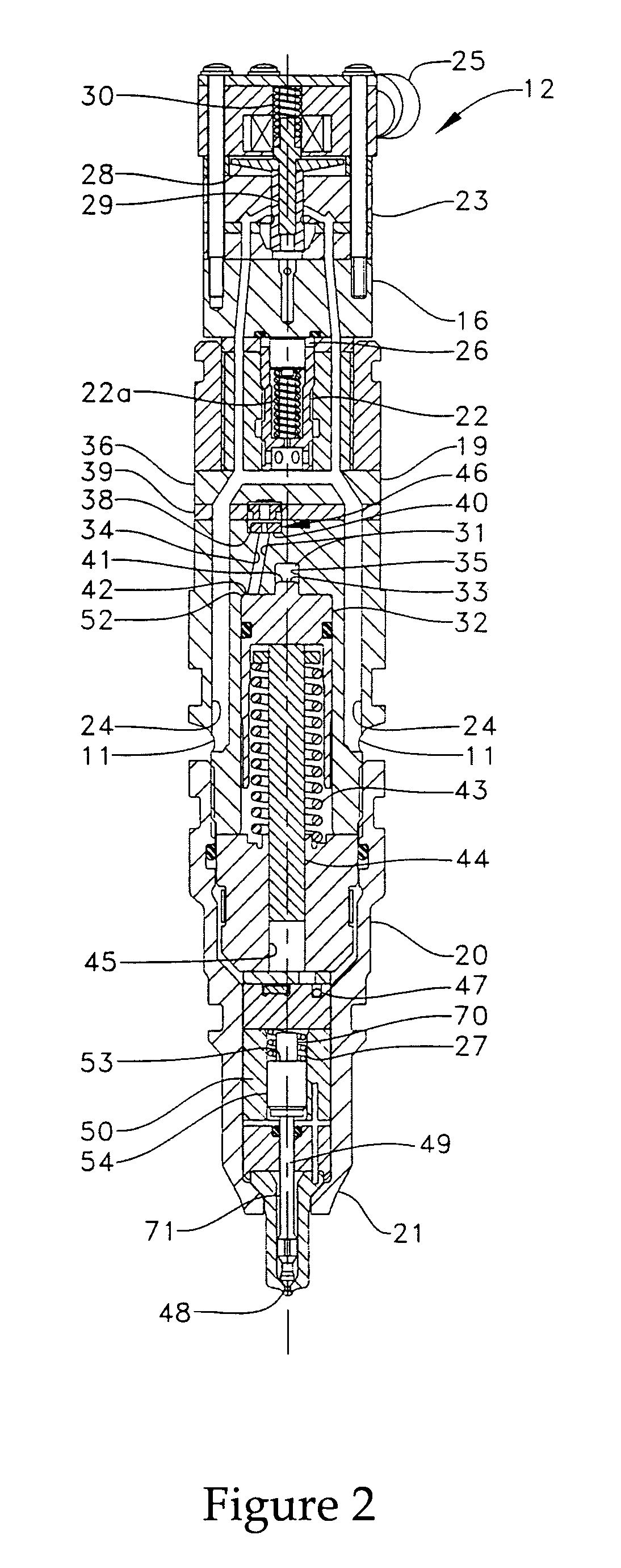
[0019]Referring to FIG. 1, there is shown a schematic representation of a fuel injection system 10, according to the present invention. The fuel injection system 10 includes at least one fuel injector 12 that includes an injector body 16 defining two actuation fluid inlets 11, an actuation fluid drain 15 and a fuel inlet 13. It should be appreciated that the present invention contemplates any number of actuation fluid inlets, including only one. Although the present invention is illustrated as including one fuel injector, it should be appreciated that the present invention can be applied in a fuel system including any number of fuel injectors, and will operate similarly within each fuel injector. A source of actuation fluid 18 and a source of fuel 17 are fluidly connected to the actuation fluid inlets 11 and the fuel inlet 13, respectfully. Although the actuation fluid could be one of various types of fluids, the actuation fluid is preferably a fluid different than the fuel, such as...


PUM


Abstract

In some fuel injectors, a variable flow rate valve is used to control actuation fluid flow rates to and from an intensifier piston. Over time, the variable flow rate valve is subjected to wear that can affect the predictability of the injection rate shape. The present invention reduces variable flow rate valve wear within a fuel injector, at least in part, by guiding a variable flow rate valve member along guide bore walls within a rate shaping path. The rate shaping path and an unrestricted path are defined by an injector body. When in a retracted position, a moveable intensifier piston includes a first hydraulic surface that is exposed to hydraulic pressure in the unrestricted path and a second hydraulic surface that is exposed to hydraulic pressure in the rate shaping path. The variable flow rate valve member defines a central passage with a predetermined flow area and includes a side surface that separates a closing hydraulic surface from an opening hydraulic surface. The side surface includes a plurality of guide surfaces that separate peripheral flow passages.

Description

TECHNICAL FIELD[0001]The present invention relates generally to fuel injectors and fuel injector systems, and more specifically to reducing wear on a valve controlling the flow rates of actuation fluid to and from an intensifier piston within the fuel injector.BACKGROUND[0002]Engineers are constantly seeking strategies for reducing engine emissions. One method of reducing engine emissions is to control numerous fuel injection variables, such as fuel pressure, spray pattern, droplet size, number of injections and injection timing. For instance, it has been found that multiple injections, including pilot and post injections, during a single combustion event reduce emissions. In order to provide multiple injections during a single combustion event with reliable consistency, a fuel injector must often have the ability to reset an intensifier piston quickly while not adversely affecting the desired injection variables.[0003]In order to reduce the amount of time the intensifier piston nee...

Claims


Application Information

Patent Timeline
Patent Type & Authority Patents(United States)
IPC IPC(8): F02M47/02F02M57/02F02M59/10
CPCF02M57/025F02M59/105Y10T137/7847
Inventor HAJI, GOUDARZ
Owner CATERPILLAR INC
Why Eureka
Try Eureka