High resolution imaging for diagnostic evaluation of the fundus of the human eye

a human eye and high-resolution imaging technology, applied in the field of ophthalmic diagnostic equipment, can solve problems such as potential problems, and achieve the effect of reducing the resolution

Active Publication Date: 2009-03-31
HEIDELBERG ENGINEERING GMBH
View PDF4 Cites 18 Cited by
  • Summary
  • Abstract
  • Description
  • Claims
  • Application Information

AI Technical Summary

Benefits of technology

[0011]When focused on the fundus, a focal point of the laser beam may generally be on the order of 6 μm×6 μm×200 μm, which is adequate for imaging much of the fundus layer. It is an important aspect of the present invention, however, that the adaptive optics are able to focus the pulses in the laser beam to spot size having about a 2 micron diameter. More specifically, it is envisioned that the pulses of the laser beam be focused to a spot size that has a PSF of approximately 2 μm×2 μm×20 μm. A smaller PSF provides for finer resolution of fundus tissue, such as the photoreceptors in the foveola.
[0012]In the operation of the system of the present invention, the laser beam is initially focused onto the fundus of the eye at a start point, and is then moved through a scanning sequence. In this scanning sequence, the laser beam is moved to a succession of focal points along a predetermined path over the fundus. Importantly, each of the laser beam's focal points is adjacent to at least one other focal point so that all of the focal points are effectively contiguous. Depending on the area of the fundus that is to be diagnosed, the path of focal points can be such that it effectively covers the desired area.

Problems solved by technology

On the other hand, misshapen and misaligned receptors, that are not substantially parallel to each other, are indicative of an unhealthy fundus and, thus, a potential problem.

Method used


Image

  • High resolution imaging for diagnostic evaluation of the fundus of the human eye
  • High resolution imaging for diagnostic evaluation of the fundus of the human eye
  • High resolution imaging for diagnostic evaluation of the fundus of the human eye

Examples


Embodiment Construction

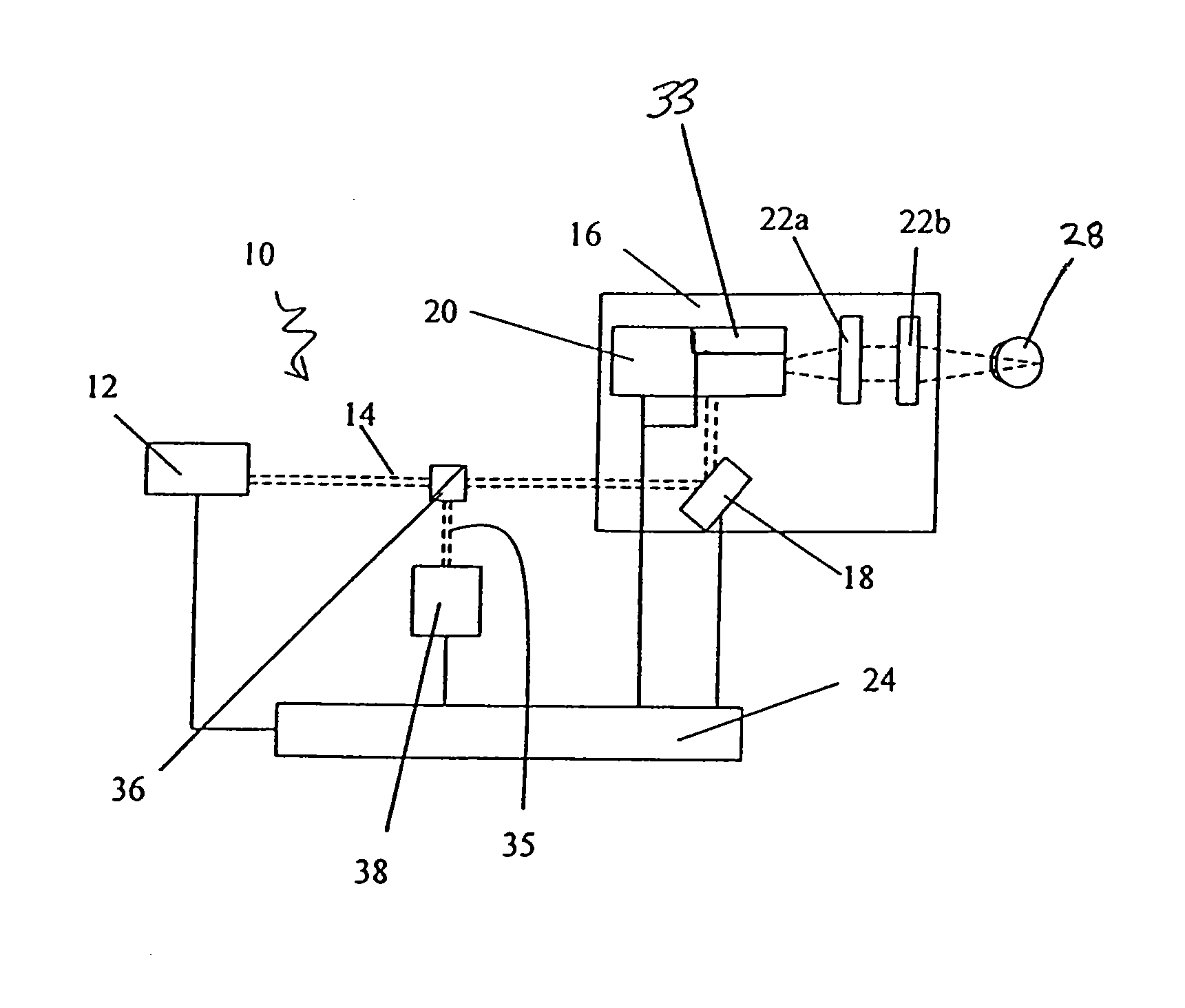
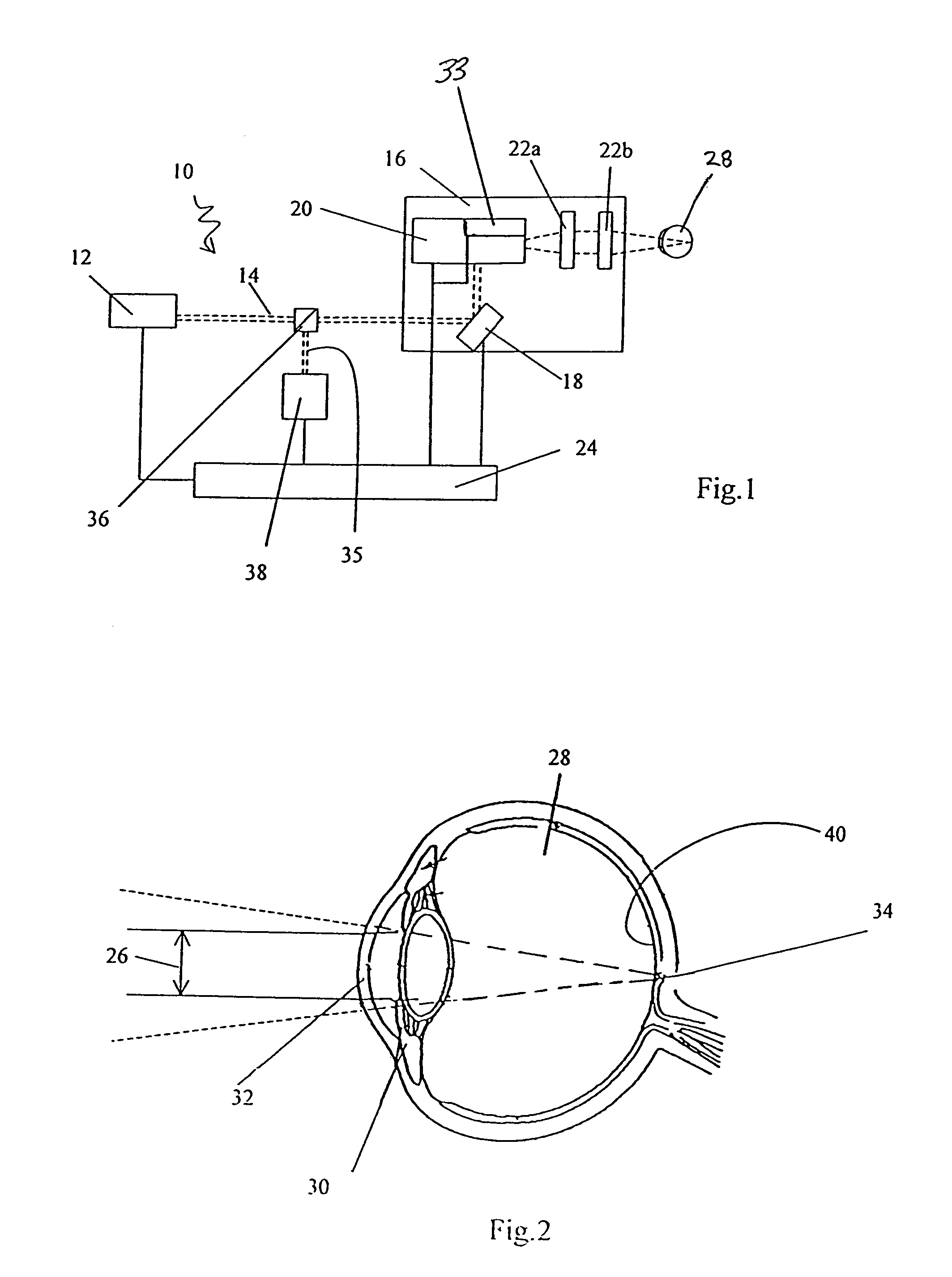
[0022]A system in accordance with the present invention is shown in FIG. 1 and generally designated 10. As shown in FIG. 1, the system 10 includes a laser source 12 for generating a laser beam 14. As contemplated by the present invention, the laser source 12 is a femtosecond (fs) laser source 12, capable of generating a laser beam 14 with a pulse repetition rate of 100 million pulses / second. Importantly, the wavelength of an individual pulse of the laser beam 14 is in the range between 700 nm to 1000 nm. In the preferred embodiment of the present invention, the laser source 12 is a tunable laser source 12, and the preferred wavelength of the laser beam 14 is 880 nm. The laser beam 14 has an energy level of 1 nJ / pulse, with a pulse duration of 100 fs.

[0023]As shown in FIG. 1, the system 10 includes an optical assembly 16 for directing and focusing the laser beam 14. In the preferred embodiment of the present invention, the optical assembly 16 includes adaptive optics which comprise a...


PUM


Abstract

A system for diagnostically evaluating the health of tissue within the fundus of an eye includes a fs laser source, an adaptive optical assembly, an imaging unit, and a computer. The adaptive optical assembly focuses a laser beam to a focal point in the fundus of the eye, and scans the fundus tissue according to a predetermined scanning pattern. Illumination of anisotropic tissue within the fundus, such as the photoreceptors and the Henle-fiber layer, induces a Second Harmonic Generation (SHG) response. Red photons, with a wavelength (λ) of about 880 nm, are converted to blue photons, with a wavelength of λ / 2, through the process of photon conversion. An imaging unit senses the blue photon return light, and uses the return light to generate an image of the fundus. The computer processes the image, and compares it to a template of healthy tissue to evaluate the health of the imaged tissue.

Description

FIELD OF THE INVENTION[0001]The present invention pertains generally to ophthalmic diagnostic equipment. More particularly the present invention pertains to a system and apparatus for evaluating the health of tissue within the fundus of an eye. The present invention is particularly, but not exclusively, useful as a system and apparatus for Second Harmonic Generation (SHG) imaging of the tissue in the fundus of a human eye to determine whether the tissue is healthy or damaged.BACKGROUND OF THE INVENTION[0002]The development of ultra-fast, ultra-short pulsed lasers as surgical tools for ophthalmic surgery has led to a need for enhanced diagnostic capabilities. For example, recent advances in optical surgery techniques include the use of femto-second (fs) lasers for intrastromal and non-invasive refractive surgery. For many of these techniques, high resolution optical imaging is required to thoroughly evaluate the precision, efficiency and effectiveness of these fs surgical lasers. In ...

Claims


Application Information

Patent Timeline
Patent Type & Authority Patents(United States)
IPC IPC(8): A61B3/02A61B3/10A61B3/14A61B3/12
CPCA61B3/1015A61B3/1225
Inventor BILLE, JOSEF F.
Owner HEIDELBERG ENGINEERING GMBH
Why Eureka
Try Eureka