Boring device

a boring device and bore technology, applied in the direction of portable drilling machines, manufacturing tools, mechanical equipment, etc., can solve the problems of pipe lining material damage, hole saw damage, and sometimes occuring positioning errors, so as to increase the inertia of the main body of the boring device, and facilitate and reliably position

Inactive Publication Date: 2009-03-31
SHONAN GOSEI JUSHI SEISAKUSHO KK
View PDF16 Cites 4 Cited by
  • Summary
  • Abstract
  • Description
  • Claims
  • Application Information

AI Technical Summary

Benefits of technology

[0012]In the boring device of the present invention, the boring blade can be easily and reliably positioned in the direction orthogonal to the longitudinal direction of the lateral pipe by the positioning means, and boring can be reliably performed without displacement of the position when a pipe lining material is bored through because the boring blade is maintained in a constant position in the direction orthogonal to the longitudinal direction of the lateral pipe by the positioning means during boring.
[0013]In the invention, a weighting member is also used to firmly press the boring blade against the pipe lining material using its weight. This also allows the inertia of the main body of the boring device to increase. Therefore, it is difficult for the boring blade to slip on the pipe lining material, and even if slippage does occur, it becomes difficult for the boring blade to move in the direction orthogonal to the longitudinal direction of the lateral pipe, and the boring blade can be prevented from colliding with the internal peripheral surface of the lateral pipe. This collision can also be reliably prevented by furthermore providing the protective cover.

Problems solved by technology

This positioning is performed while monitoring the inside of the main pipe using the TV camera, but since the inside of the main pipe is dark and yields poor visibility, errors sometimes occur in positioning, specifically, in the boring position.
Therefore, it is difficult to position the hole saw in the desired boring position (in the center of the opening at the end of the lateral pipe, or another position, for example) in the orthogonal direction inside the lateral pipe, and the boring position is sometimes displaced from the desired position.
In this case, the hole saw is damaged, the pipe lining material suffers damage when a lateral pipe is being lined, or other such drawbacks occur.

Method used


Image

  • Boring device
  • Boring device
  • Boring device

Examples


second embodiment

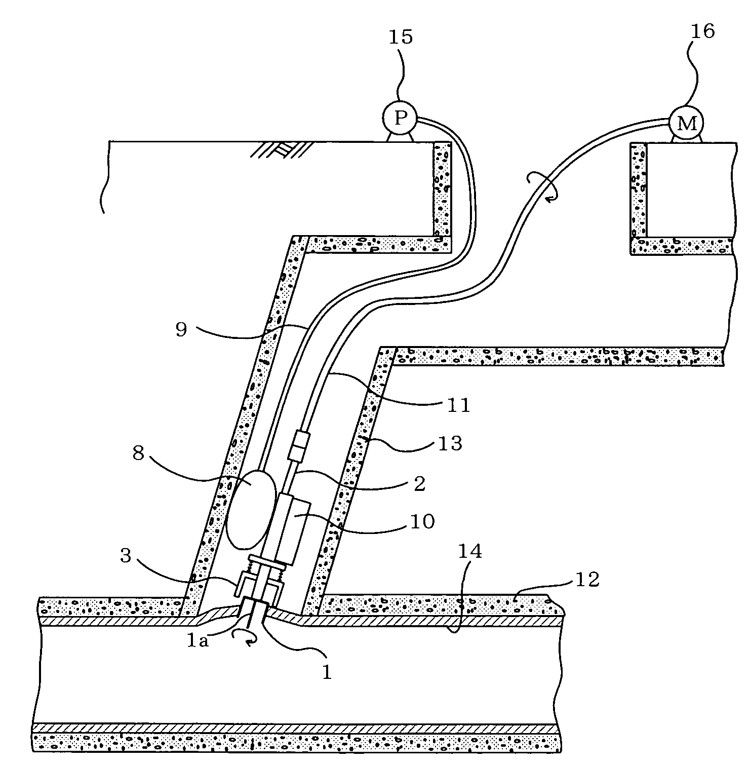
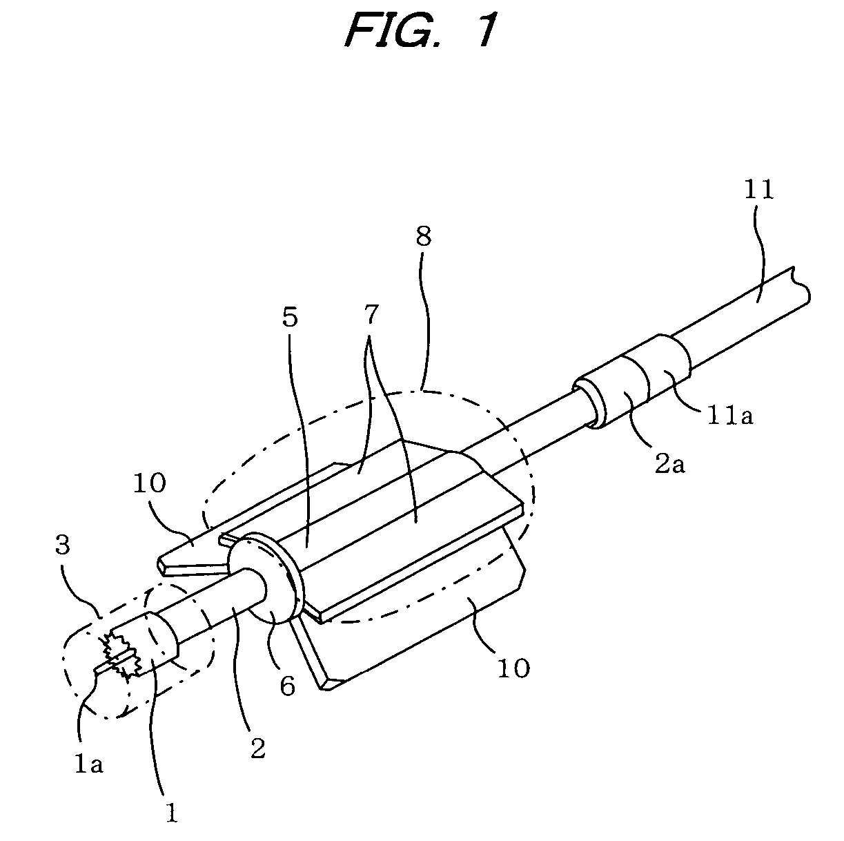
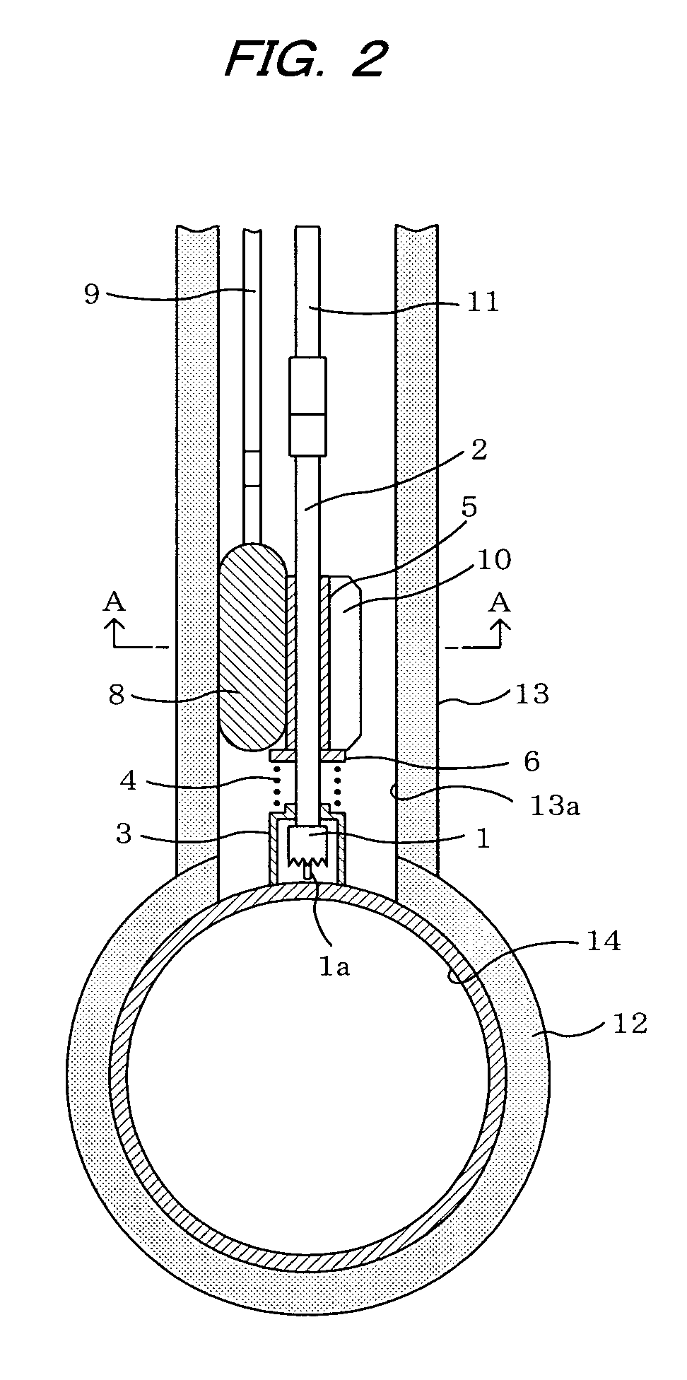
[0039]FIG. 5 shows a boring device according to the present invention. In FIG. 5, the main body of the boring device is positioned inside the lateral pipe 13, the same as in the embodiment of FIG. 2. The same symbols are used in FIG. 5 for components that are the same as those in FIG. 2, and description thereof is omitted.

[0040]In FIG. 5, the boring device is configured so that weighting members 17 can be mounted on the main body of the boring device. FIG. 5 shows a state in which three weighting members 17 are mounted, but any number of weighting members may be mounted.

[0041]The weighting members 17 weigh down on the hole saw 1 and are formed from metal or the like in a thick-walled cylindrical shape having a hole formed through the center thereof. Weighting members are mounted in the interval from the proximal end (the top end in FIG. 5) of the rotating shaft 2 to the distal end (the bottom end in FIG. 5) of the flexible shaft 11.

[0042]A disk-shaped weight stopper 18 for catching ...

first embodiment

[0043]Grease or lubricating oil is applied in advance to the undersides and internal peripheral surfaces of the holes of the weighting members 17 in order to prevent the friction of the weighting members 17 from impeding the rotation of the rotating shaft 2 and flexible shaft 11 as much as possible. Other aspects of this configuration are the same as those in the

[0044]With the boring device of the second embodiment thus configured, the portion of the pipe lining material 14 of the main pipe 12 that blocks the opening at the end of the lateral pipe 13 is bored through from the side of the lateral pipe 13, in the same manner as by the apparatus of the first embodiment. At that time, the desired number of weighting members 17 are first stacked onto the weight stopper 18 as described above and mounted when the joints 2aand 11a are linked together, before the main body of the boring device is inserted into the lateral pipe 13.

[0045]The main body of the boring device to which the air hose...


PUM

PropertyMeasurementUnit
obtuse angleaaaaaaaaaa
flexibleaaaaaaaaaa

Abstract

A boring device is inserted into a lateral pipe to bore a pipe lining material inserted into a main pipe across the lateral pipe intersecting therewith and a portion of which blocks an opening of the lateral pipe that communicates with the main pipe. The boring device has a rotatable shaft, a bearing member for rotatably bearing the rotatable shaft, and a boring blade mounted on the rotatable shaft for rotation therewith to bore through the portion of the pipe lining material that is blocking the opening of the lateral pipe. A supporting member is mounted on one side of the bearing member. An inflatable bag is mounted on the other side of the external periphery of the bearing member. The inflatable bag is inflatable in the lateral pipe so that the inflatable bag and the supporting member are pressed against an internal peripheral surface of the lateral pipe.

Description

BACKGROUND OF THE INVENTION[0001]1. Field of the Invention[0002]The present invention relates to a boring device inserted into a lateral pipe to bore a pipe lining material that is inserted into a main pipe across the lateral pipe intersecting therewith.[0003]2. Description of the Prior Art[0004]A lining construction method has been proposed in the past for lining an existing pipe using a pipe lining material in order to rehabilitate an existing pipe without unearthing the pipe when a buried sewer line or other existing pipe has deteriorated with age (see JP-A 6-114939). The pipe lining material is a resin absorbent material composed of a tubular flexible nonwoven cloth impregnated with an uncured liquid curable resin (generally a thermosetting resin), formed so as to conform to the shape of the existing pipe. A highly airtight plastic film is attached to the outer circumferential surface of the resin absorbent material. In this construction method, fluid pressure is used to invert ...

Claims


Application Information

Patent Timeline
Patent Type & Authority Patents(United States)
IPC IPC(8): B23B41/08
CPCF16L55/179Y10T408/55Y10T409/304424Y10S408/714Y10T408/675Y10T408/557Y10T408/5665B26F1/16
Inventor KAMIYAMA, TAKAOKANETA, KOJIFUJII, KENJI
Owner SHONAN GOSEI JUSHI SEISAKUSHO KK
Why Eureka
Try Eureka