Machinable composite mold

a composite material and machine-machine technology, applied in the field of machine-machine-made composite materials, can solve the problems of increasing the cycle time of composite structure molding, heavy and expensive steel alloy molds, and difficult machine or repair

Active Publication Date: 2009-03-31
HEXCEL
View PDF11 Cites 29 Cited by
  • Summary
  • Abstract
  • Description
  • Claims
  • Application Information

AI Technical Summary

Problems solved by technology

Although steel alloy molds are well suited for their intended purpose, there are a number of drawbacks associated with the use of steel alloy molds.
For example, steel alloy molds tend to be heavy and expensive.
In addition, the time required to heat and then cool a massive steel alloy mold increases the cycle time during molding of composite structures.
A problem with composite molds is that they are difficult to machine or repair.
In addition, it is difficult to process the mold to obtain tight surface tolerances or accommodate changes in the profile of the mold surface without degradation of vacuum integrity and compromising dimensional stability.
This problem arises because machining the surface of the mold exposes the heavier weight woven material and changes the quasi-isotropic characteristics of the laminate.
The removal of layers of different weight material also leaves an unbalanced laminate that can distort and affect the dimensional integrity of the mold and compromise vacuum integrity.
In addition, the heavier weight materials tend to be porous due to the woven characteristics of the material.
When machining into these layers, the porosity affects vacuum integrity and vacuum leaks can develop along the interlaminar shear planes that are formed due to the material being applied to the master mold as layers.
Machining of composite molds is further complicated because the resins used in composite molds tend to be brittle.

Method used


Image

  • Machinable composite mold
  • Machinable composite mold
  • Machinable composite mold

Examples


Embodiment Construction

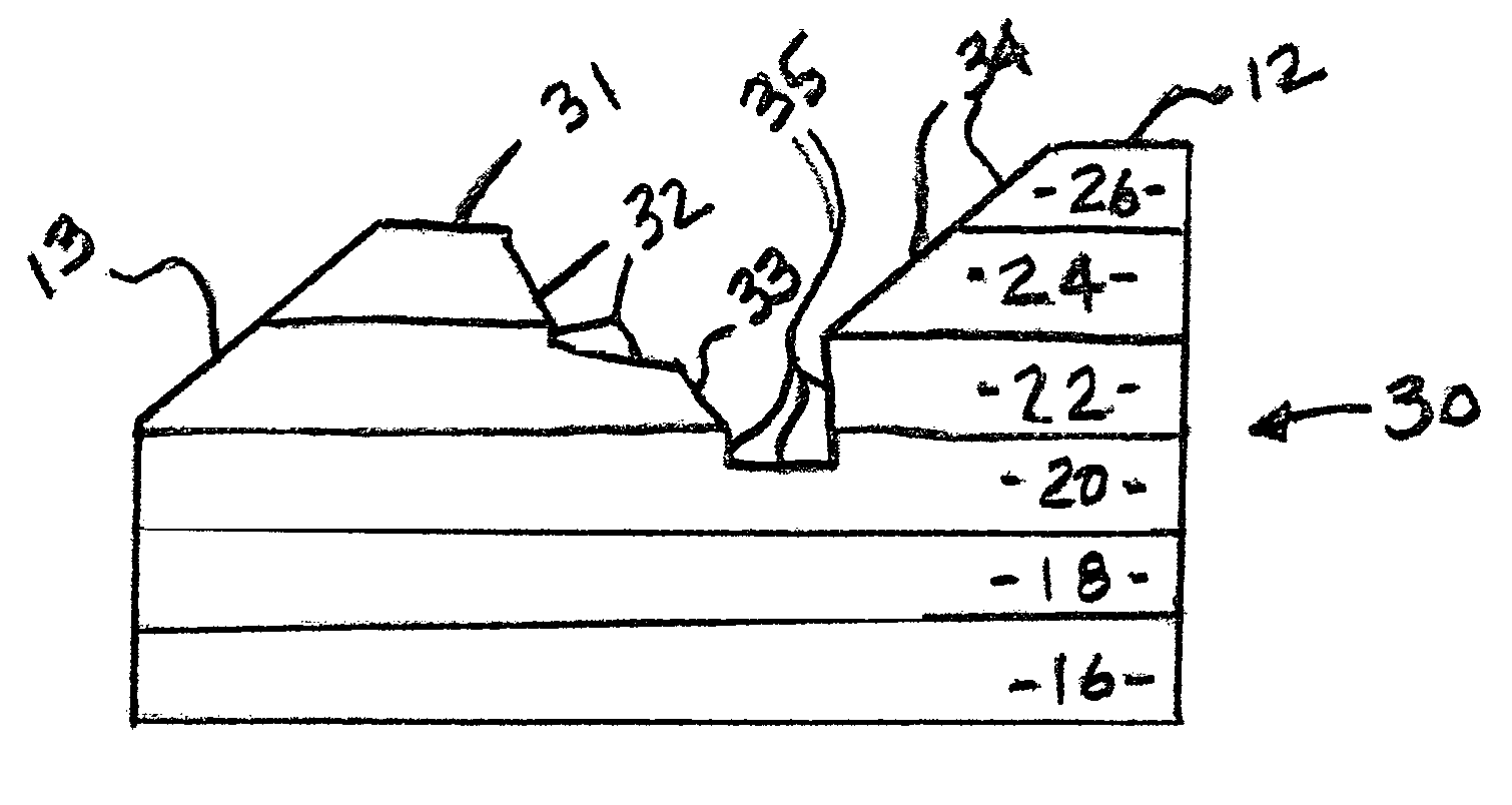
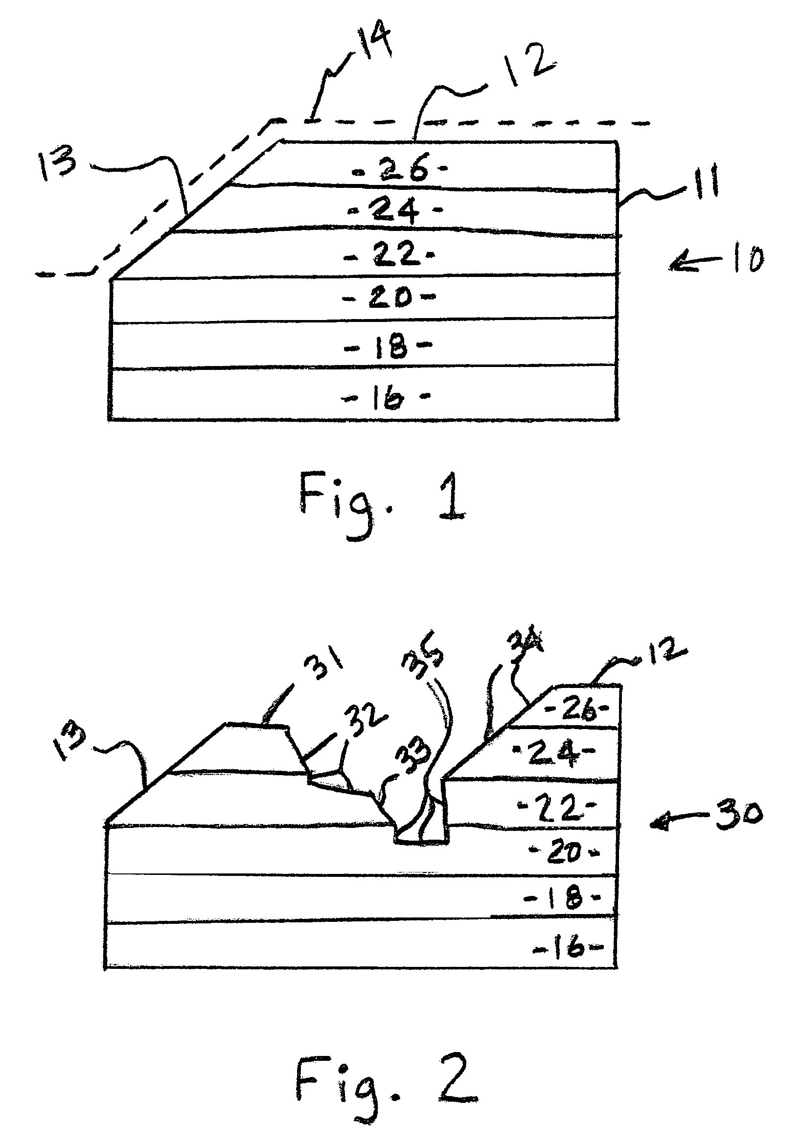
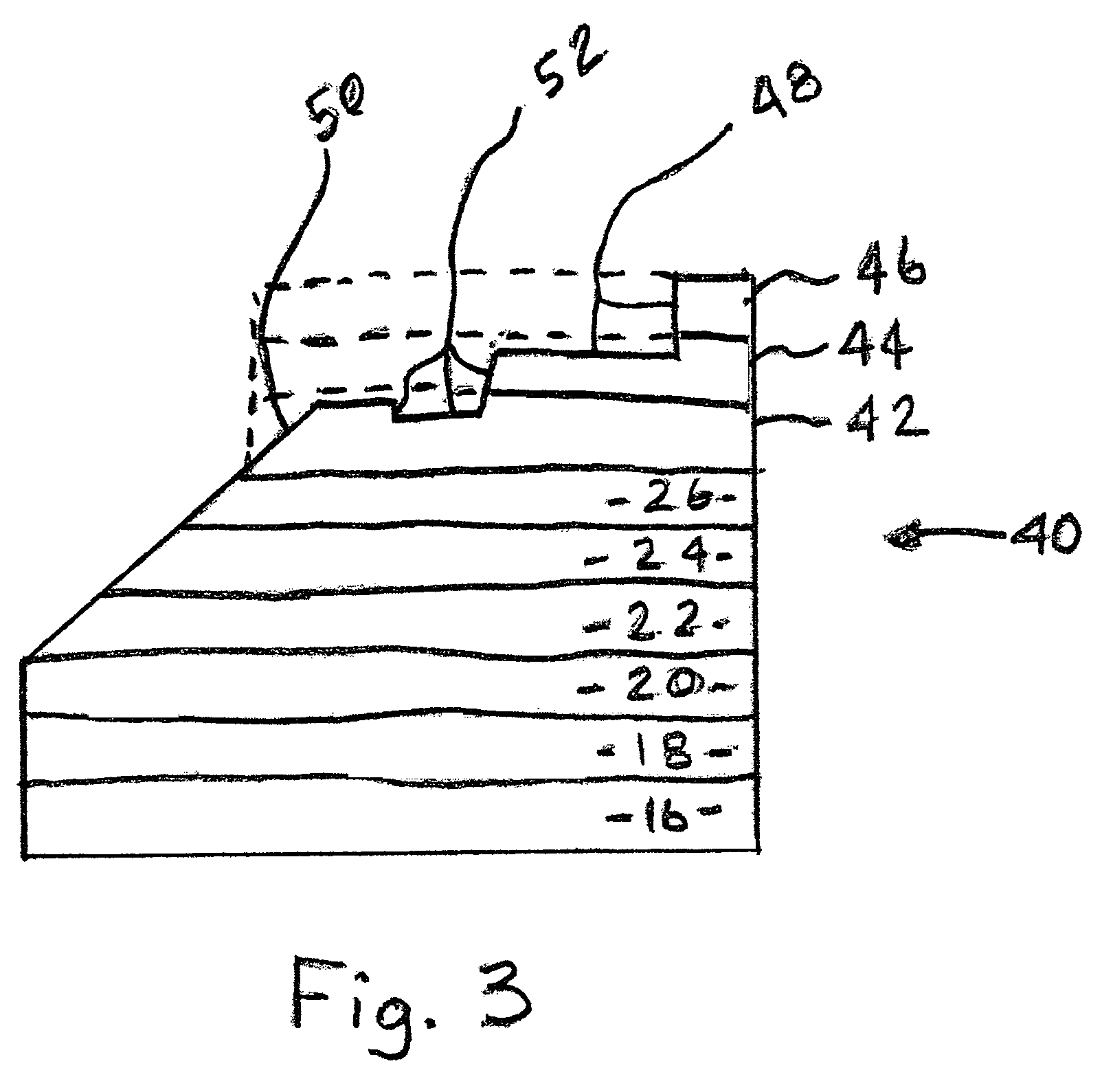
[0019]A portion of an exemplary composite mold in accordance with the present invention is shown diagrammatically at 10 in FIG. 1. The mold is intended for use in fabricating composite parts in accordance with known autoclave curing processes where service temperatures are typically between 350° F. and 500° F. However, if desired, the mold may be used in other molding processes where it is not necessary to heat the material being molded. The mold 10 is designed as a replacement for existing composite molds or tooling that are typically supported by another structure during the molding process. These types of composite molds have been in use for many years to mold a wide variety of composite materials. The molds of the present invention may be used in any situation where such a composite mold is required.

[0020]The mold 10 includes a mold body 11 that has tool surfaces 12 and 13 that are shaped to provide the desired molded surface on the composite structure that is being fabricated. ...


PUM

PropertyMeasurementUnit
volume percentaaaaaaaaaa
cure temperaturesaaaaaaaaaa
temperaturesaaaaaaaaaa

Abstract

Machinable composite molds for use in making a composite structure. The mold includes a mold body having a tool surface that is shaped to provide the molded surface of the composite structure. The mold body is made up of at least one mold layer composed of a quasi-isotropic material composed of a plurality of randomly oriented fiber bundles or chips impregnated with a resin. The use of randomly oriented fiber chips allows post-cure machining of the mold body.

Description

BACKGROUND OF THE INVENTION[0001]1. Field of the Invention[0002]The present invention relates generally to apparatus and methods used to mold composite materials to form composite structures. More particularly, the present invention is directed to the molds / tools that are used to form such composite structures.[0003]2. Description of Related Art[0004]Many processes for making composite structures utilize a mold or tool to provide desired surface contours and shapes. The mold is particularly important in autoclave processes where the uncured resin / fiber material is heated in the mold, under vacuum, to relatively high cure temperatures (350° F. and above) to form the final composite part or structure.[0005]Molds made from steel alloys, such as INVAR36, are being presently used because they are extremely strong and can easily withstand the elevated cure temperatures used in autoclaves for composite material curing. These molds are also commonly referred to as “tools” or “tooling”. Stee...

Claims


Application Information

Patent Timeline
Patent Type & Authority Patents(United States)
IPC IPC(8): B29C33/40
CPCB29C33/38B29C33/3842Y10T156/10B29K2105/12B29C33/3857Y10T428/31721
Inventor CALLIS, RICHARD A.
Owner HEXCEL
Why Eureka
Try Eureka