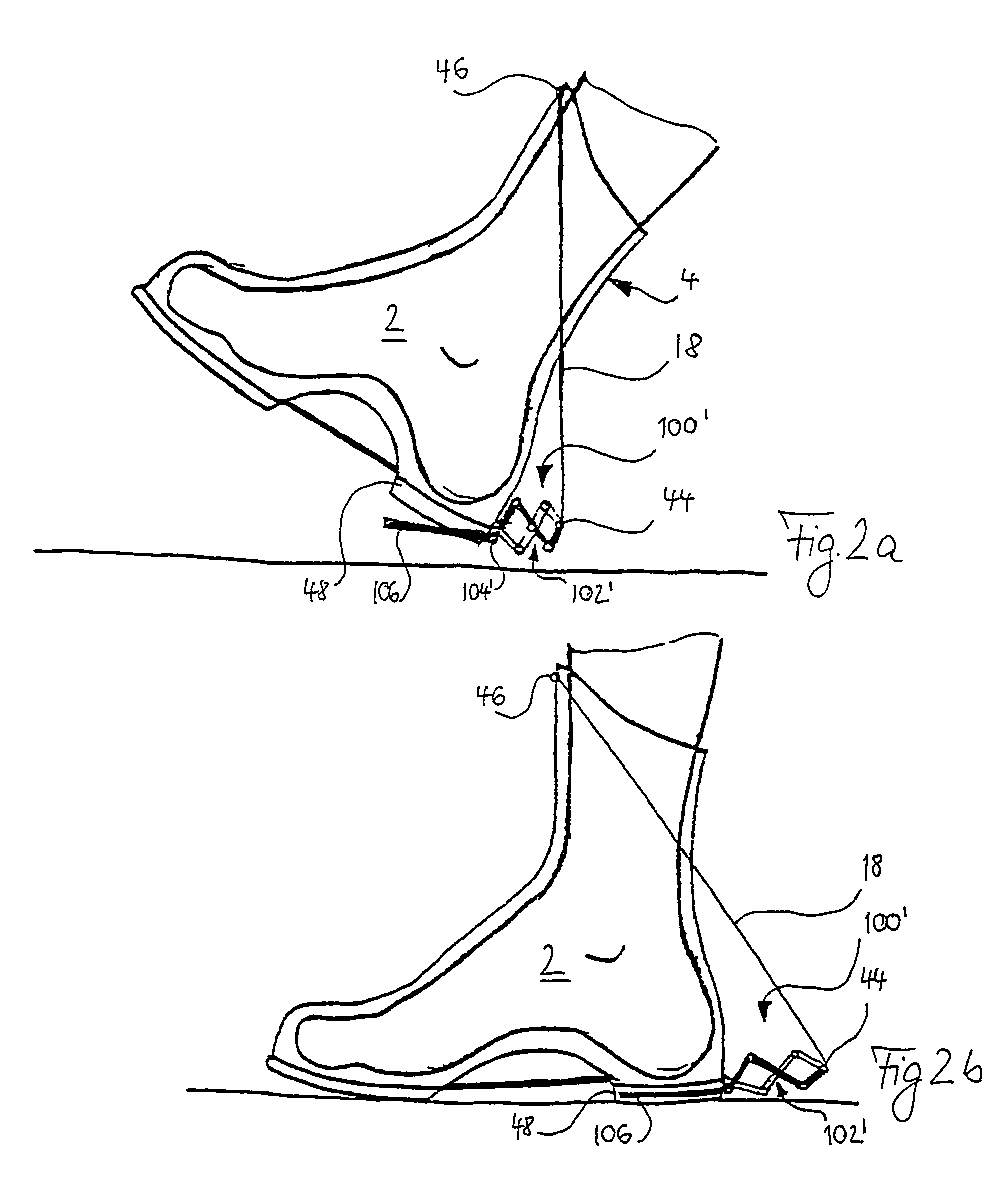
[0020]A further alternative embodiment resides in a member extending spike-like rearwards in the form of a pneumatic or
hydraulic cylinder with the
appendage for the tension element, which can be pneumatically or hydraulically extendably operated and which communicates with a pressure chamber via a fluid line. The pressure chamber is then arranged under the sole of the shoe, so that setting down of the shoe on the floor during a step has the effect that pressure from the pressure chamber acts upon the
piston and accordingly the
piston is extended. Accordingly, the member is elongated rearwardly and / or downwardly and so stretches the base spring element.
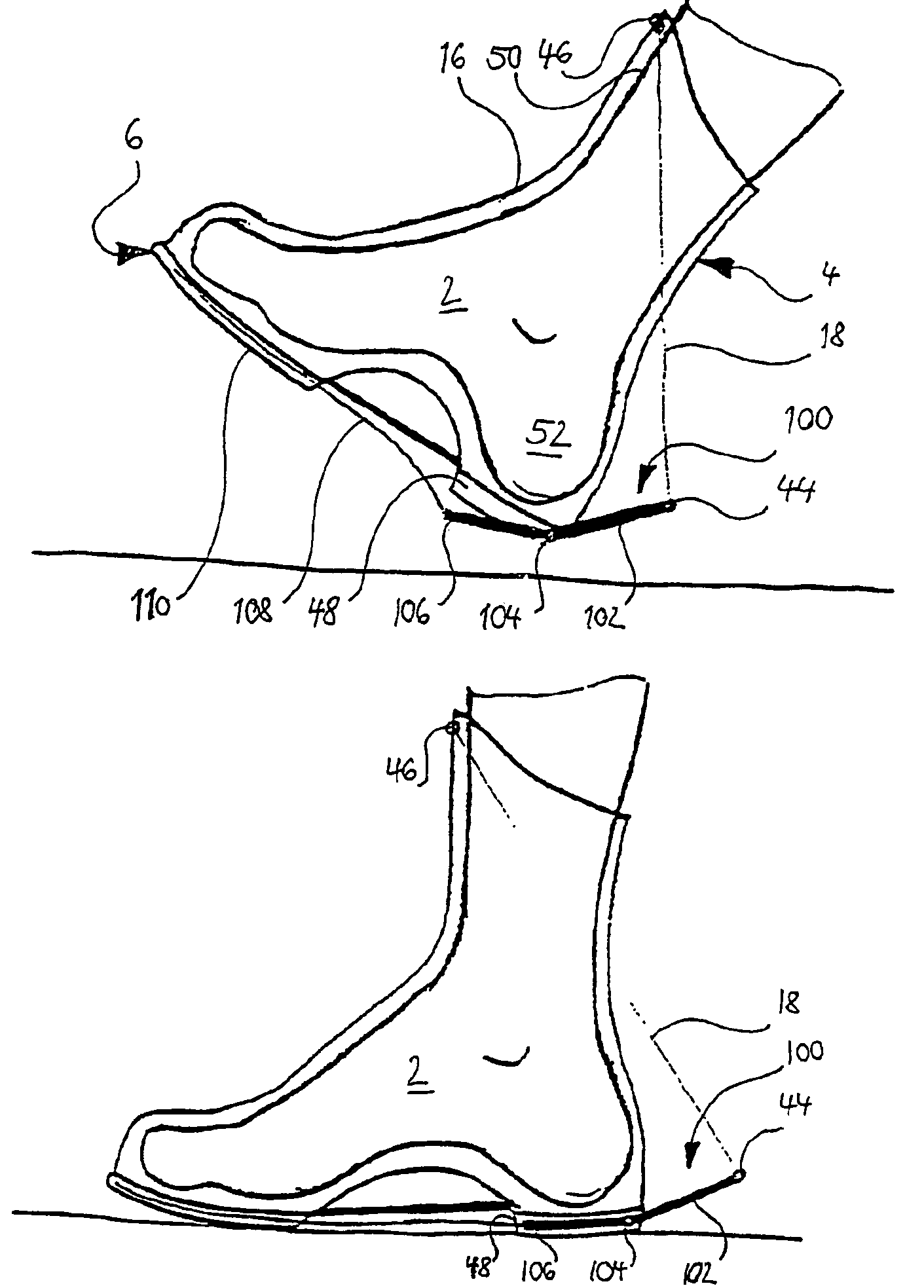
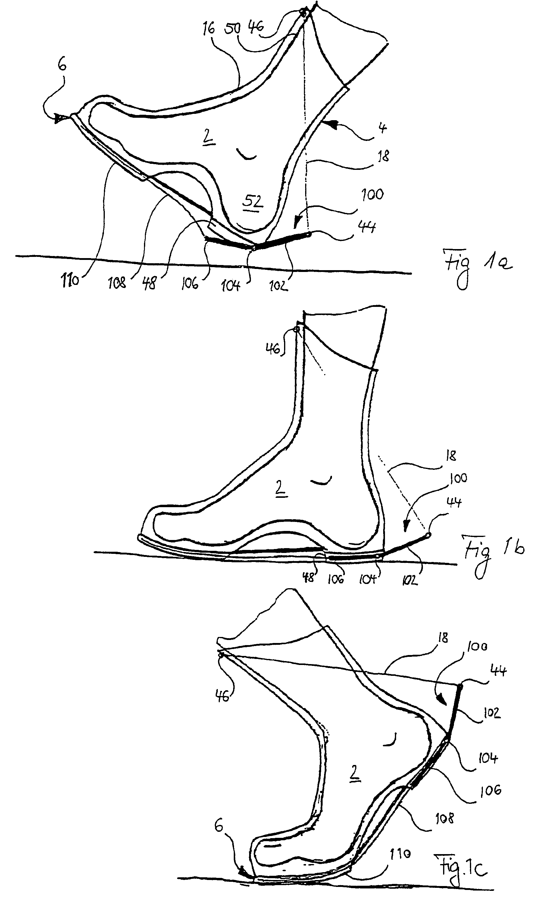
[0024]In virtue of the fact that, in the
system between the shin and the heel (from above to below: shin via the
ankle joint to the heel bone) the series of bones already forms a
concatenation of support elements and the expansion of the base spring element at the time of planting of the
forefoot during ambulation is supported (the associated “lifting” of the tip of the foot and simultaneous removal of the rear end of the foot (heel) as an appendage point of the base spring element from its other appendage point at the
front edge of the shin bone) by these bones, an artificial support element, which is integrated into the shoe, can also be eliminated. But even an additional support of this stretching via an artificial support element between the appendage point of the base spring element at the heel and the appendage point of the base spring element at the front edge of the shin bone is in accordance with the invention.
[0027]Natural collagen fibers which also comprise the tendons and ligaments in the
human body, are elastic as has already been described. Furthermore, they have the characteristic of not being linearly elastically deformable but deform in the area of lesser expansion with lower elastic force (thus “easier”) and in contrast, in the zone of greater expansion, they operate an over-proportionally great elastic force (they are thus “more difficult” to deform). This non-
linear elasticity of the natural tendons and ligaments consequently effects firstly the already described effect of
energy storage and energy release and secondly prevents the destruction of structures because of excessive stretching. This feature is preferred in accordance with the invention for the base spring element, which then expands elastically preferably up to a constructively pre-defined or even adjustable degree (for
energy storage and release) and which “opposes”, however, with increased rigidity further expansion upon greater stretch. In this zone, then, the flexing of the foot is limited by the greater rigidity of the base spring element and effects, in corresponding configuration, that the force introduced into the floor from the foot is used essentially only for pressing and consequently for “advance propulsion” of the foot.
[0029]The rigidity of the base spring element can be adjusted to be different from the respective function (sports, routine, impaired) or to the individual situation. Gliding during the stretch of the preferably longitudinal, loosely flexible structure of the base spring element can accordingly be facilitated by means of sleevelike structures (such as the natural
tendon sheaths), in order to maximally prevent
energy loss, which can occur due to friction. A padding at the contact points, especially at the shin bone, also to make possible a larger areas of force induction by means of the
skin, is preferred. Accordingly, the contact points can have an adjusting piece formally adapted to the front edge of the shin bone, which can be integrated into the shoe shaft, for example. However, it can also—e.g. in order to position the appendage point on the front edge of the shin bone as far as possible upwards in the direction of the knee—be integrated in a sleeve, for example, and the appendage point on the front edge of the shin bone s then supported by means of the support element downwards towards the shoe and there supported in particular in the heel zone.
[0032]In order not to “waste” energy for compensatory movements, the sole of the shoe according to the invention is preferably provided with suitable structures for improving surface grip and
impact damping. For improving surface grip profile corrugations in the underside of the shoe sole, but also “spikes” or “cleats” are suitable, which can even be replaceable. For damping purposes, for example, elements, whose material properties effect a specific damping and which can also be replaced with elements having other damping characteristics for adjustable
adaptation of the damping relationship are suitable.

