Transport system

a technology of transport system and current-heat loss, which is applied in the field of transport system, can solve the problems of high current-heat loss in the travel rail, and achieve the effect of reducing material and assembly expenditure and reducing current-heat loss in the induction conductor

Inactive Publication Date: 2009-03-31
DUERR SYST GMBH
View PDF11 Cites 18 Cited by
  • Summary
  • Abstract
  • Description
  • Claims
  • Application Information

AI Technical Summary

Benefits of technology

[0008]Because of the presence of the induction conductor, which is arranged in the vicinity of the supply conductor, the inductance of the stationary conductor loop comprising the supply conductor in the transport system according to the invention is reduced. A return conductor directed back parallel to the supply conductor along the travel path of the transport system is not necessary in the transport system according to the invention, and therefore the transport system according to the invention manages with a lower material and assembly expenditure.
[0009]Moreover, the current induced in the induction conductor is constantly lower than the current impressed by the supply conductor, as a result of which the current-heat losses arising in the induction conductor are reduced.
[0015]A particularly low inductance of the conductor arrangement is achieved if the first supply conductor feed section and the first short-circuit conductor section are run together in a multicore supply cable at least in sections.
[0027]The inductance of the conductor arrangement comprising the two supply conductor feed sections can be reduced in this path.
[0047]In a preferred configuration of the transport system according to the invention, it is provided that the conductor system of the transport system has no return conductor, and as a result of this a considerable material and assembly expenditure can be saved compared to transport systems with a return conductor.
[0053]As a result of the curvature of the travel path and the induction conductor it is possible to arrange the end regions of the induction conductor as closely as possible to one another, so that the short-circuit conductor, which short-circuits the end regions of the induction conductor to one another, can be kept as short as possible.

Problems solved by technology

If the return conductor is directed back close to a travel rail of the transport system, then eddy currents are induced in the travel rail, which result in current-heat losses.
In such transport systems, the current flowing in the travel rail is equal to the current in the supply conductor, which results in correspondingly high current-heat losses in the travel rail.

Method used


Image

  • Transport system
  • Transport system
  • Transport system

Examples


first embodiment

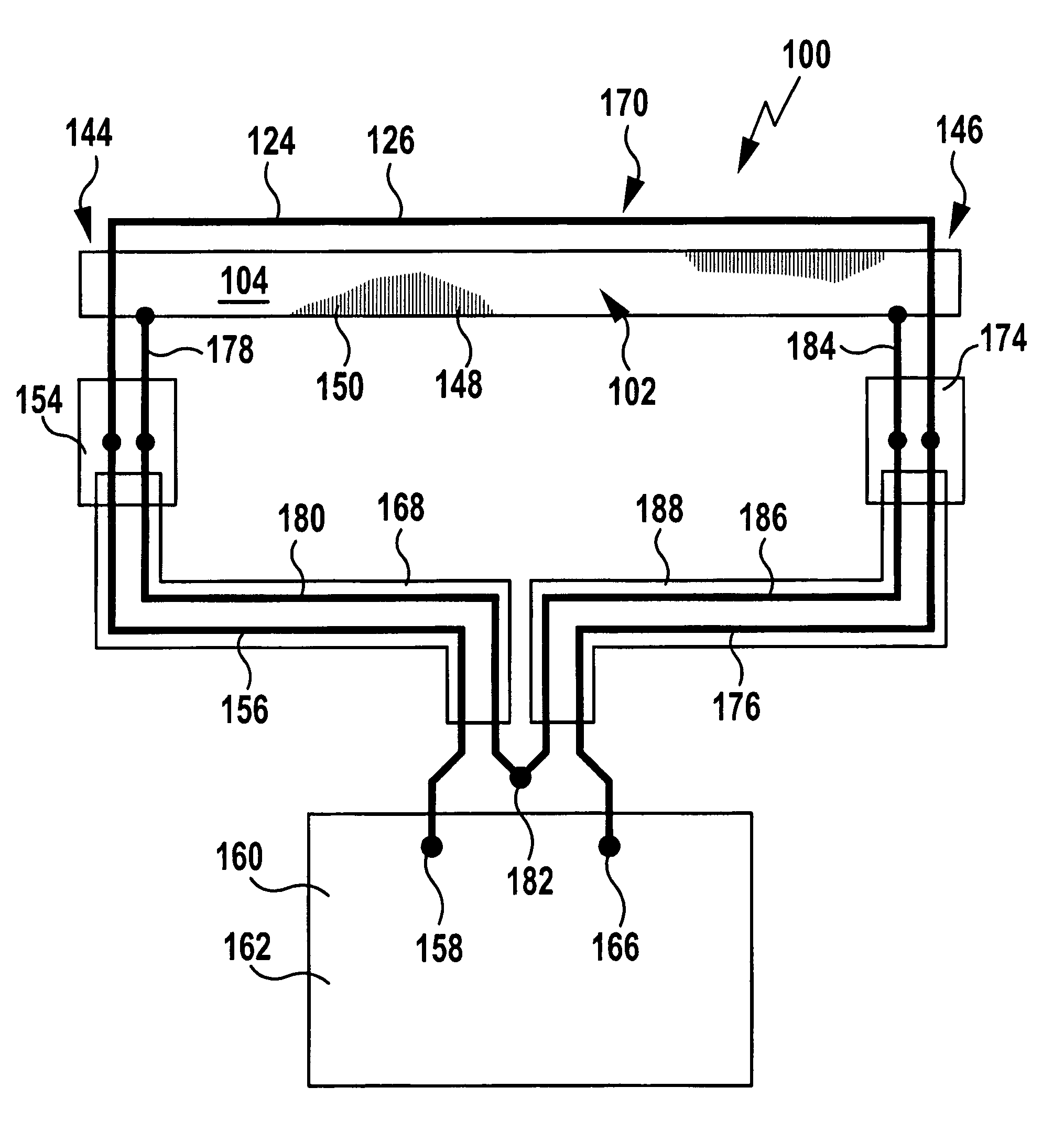
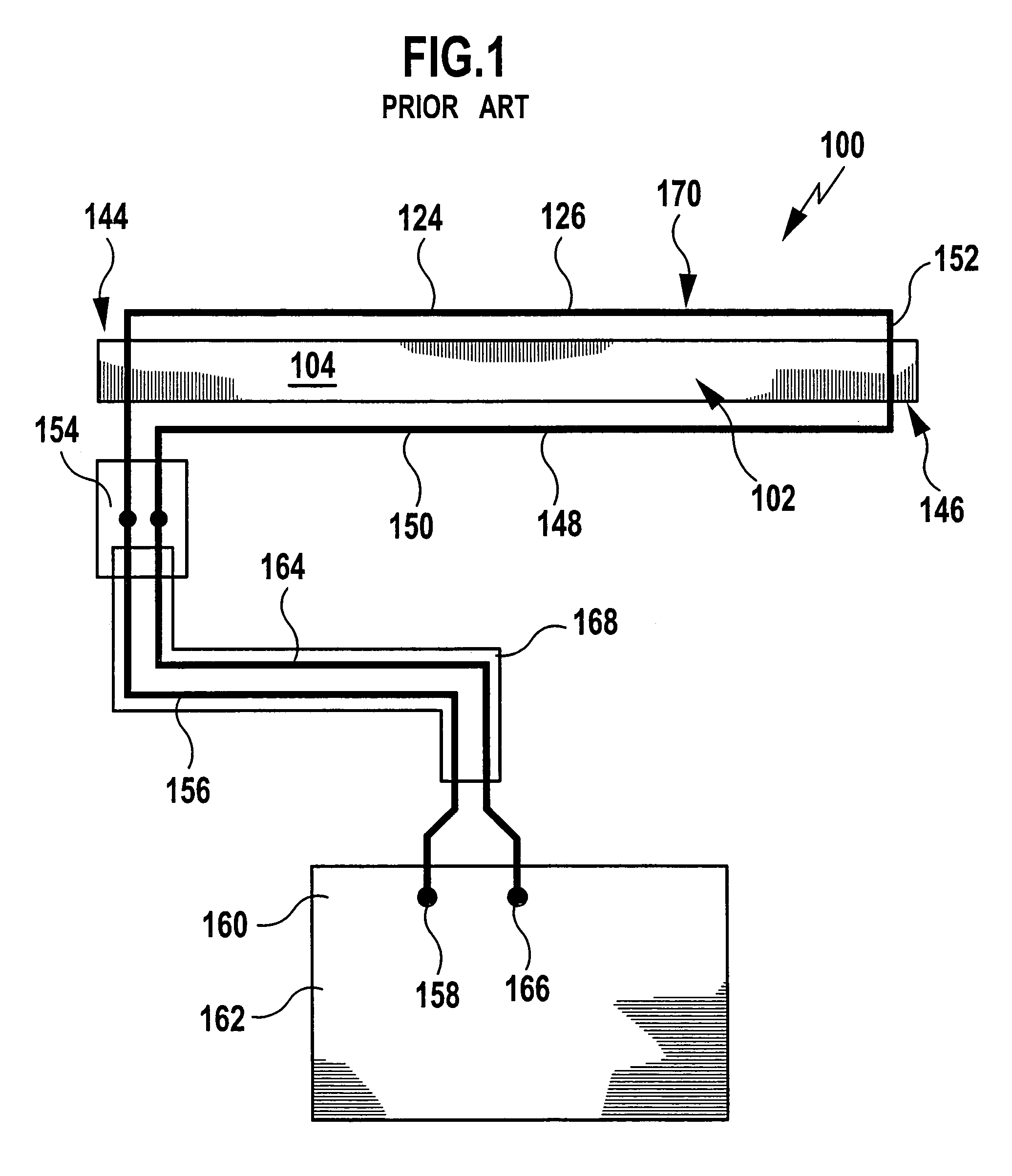
[0094]a transport system 100 according to the invention shown in FIGS. 5 to 7 differs from the transport system 100 shown in FIGS. 1 and 2 in that no return conductor 150 is present.

[0095]Instead, the supply conductor travel path section 124 in the second end region 146 of the travel rail 104 is led into a second connection box 174 and there is connected to a second supply conductor feed section 176, which connects the supply conductor travel path section 124 to the second output 166 of the medium frequency generator 162 serving as energy source 160 of the transport system 100.

[0096]In the first end region 144 of the travel rail 104 the supply conductor travel path section 124 is led into a first connection box 154 and there is connected to a first supply conductor feed section 156, which connects the supply conductor travel path section 124 to the first output 158 of the medium frequency generator 162.

[0097]In this embodiment, the travel rail 104 is electrically separated from the ...

third embodiment

[0126]a transport system 100 according to the invention shown in FIG. 9 differs from the first embodiment shown in FIGS. 5 to 7 merely in that the travel path 102 is not rectilinear, but comprises a curve with an essentially quarter-circle-shaped travel path section 200.

[0127]In this embodiment, the travel rail 104 also comprises a section 202 curved essentially in a quarter-circle shape. As a result of the arc-shaped curvature of the travel path 102 and the travel rail 104 the end regions 144 and 146 of the travel rail 104 lie more closely adjacent to one another than in the case of the above-described first embodiment, and therefore the length of the supply cables 168, 188 can be reduced, in particular when the medium frequency generator 162 serving as energy source 160 of the transport system 100 is arranged approximately in the centre between the two end regions 144 and 146.

second embodiment

[0128]As in the case of the above-described second embodiment, it can also be provided with this embodiment that the travel rail 104 is divided into several travel rail sections 194 arranged consecutively along the travel path 102.

[0129]Otherwise, the third embodiment shown in FIG. 9 is the same with respect to its structure and function as the first embodiment shown in FIGS. 5 to 7, and reference is made to the above description thereof on this basis.

[0130]A fourth embodiment of a transport system 100 according to the invention shown in FIG. 10 differs from the above-described third embodiment in that the travel path 102 not only comprises a single quarter-circle-shaped travel path section 200, but two such quarter-circle-shaped travel path sections 200, which are curved in the same direction, so that the travel path 102 has the shape of a U overall.

[0131]In this embodiment, the travel rail 104 also has two essentially quarter-circle-shaped travel rail sections 202 curved in the sa...


PUM


Abstract

In order to provide a transport system with a conductor system, which includes at least one supply conductor, which is connected to an energy source, at least one transport carriage movable along a travel path relative to the conductor system and at least one device for the non-contact transmission of energy from the conductor system to the transport carriage, in which transport system the stationary conductor loop has an inductance that is as low as possible and in which ohmic losses are kept as low as possible, it is proposed that the transport system includes at least one induction conductor, which at least in sections is arranged so closely adjacent to the supply conductor that an electric current flowing in the supply conductor generates an induction current in the induction conductor, wherein the induction conductor has at least two end regions, which are short-circuited to one another, and / or wherein the induction conductor is closed in a ring shape.

Description

RELATED APPLICATION[0001]This application is a continuation application of PCT / EP2004 / 004351 filed Apr. 24, 2004, and claims priority to German patent application number 103 26 614.3, filed Jun. 13, 2003, all of which are hereby incorporated by reference.FIELD OF THE DISCLOSURE[0002]The present invention relates to a transport system, in particular a rail-mounted transport system, e.g. a suspension monorail, which comprises at least one supply conductor, which is connected to an energy source, at least one transport carriage movable along a travel path relative to the conductor system and at least one device for the non-contact transmission of energy from the conductor system to the transport carriage.BACKGROUND[0003]Such transport systems are known from the prior art.[0004]In particular, known from the prior art are such transport systems, in which the conductor system comprises a supply conductor extending along the travel path and a return conductor, which is connected in series ...

Claims


Application Information

Patent Timeline
Patent Type & Authority Patents(United States)
IPC IPC(8): H05B6/10B60L5/00B60L9/00B60L13/00H02J17/00
CPCB60L5/005B60L2200/26B60Y2200/30
Inventor LINDIG, ERIK
Owner DUERR SYST GMBH
Why Eureka
Try Eureka