Rotary variable capacitance element and rotary variable capacitance device
a variable capacitance and capacitance element technology, applied in the direction of mechanically variable capacitor details, non-mechanically variable capacitors, capacitors, etc., can solve the problems of increasing the power consumption of the variable capacitance element 102 and the variable capacitance device, and achieve the effect of small power consumption and large electrostatic capacitan
- Summary
- Abstract
- Description
- Claims
- Application Information
AI Technical Summary
Benefits of technology
Problems solved by technology
Method used
Image

Examples
first embodiment
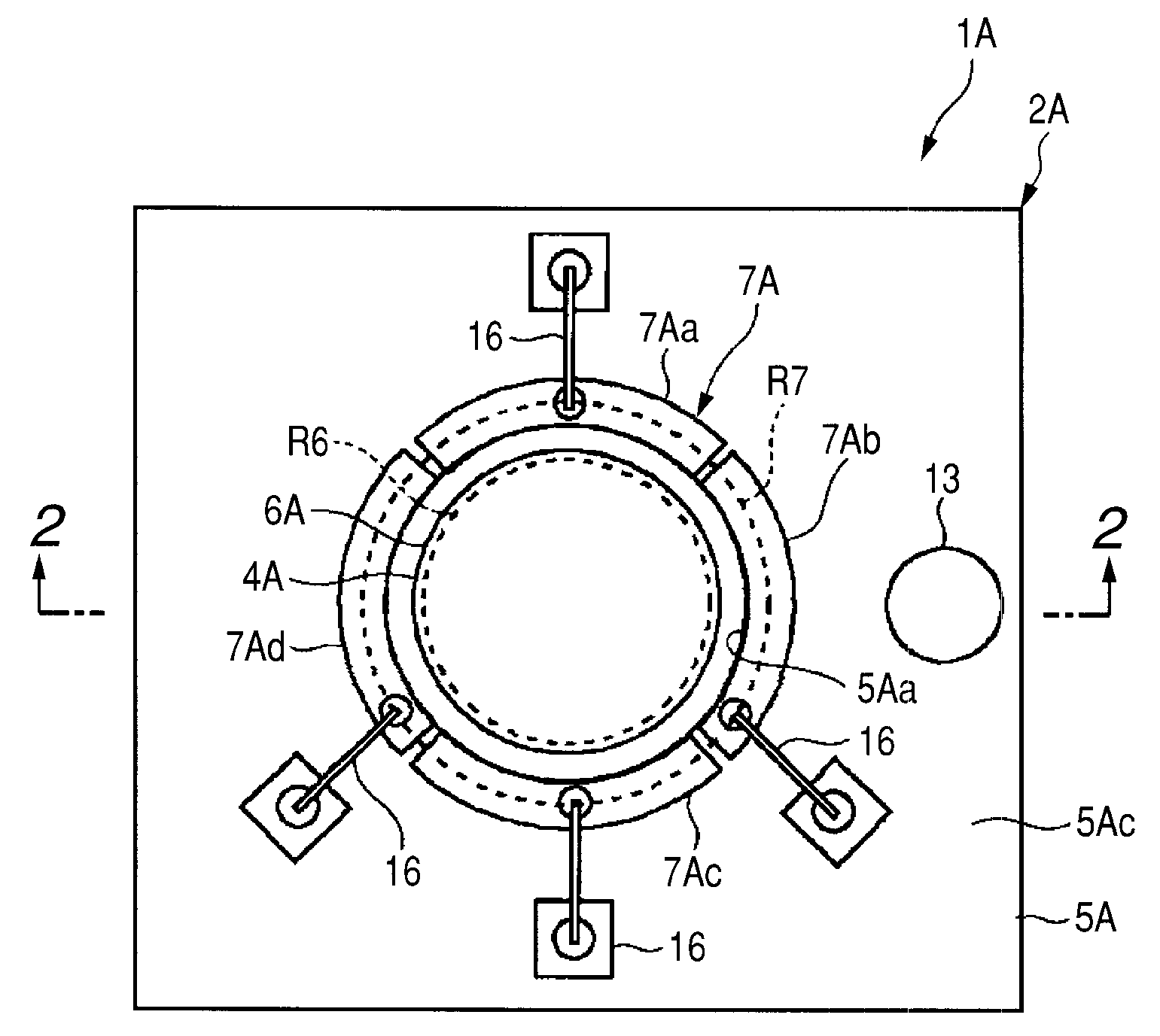
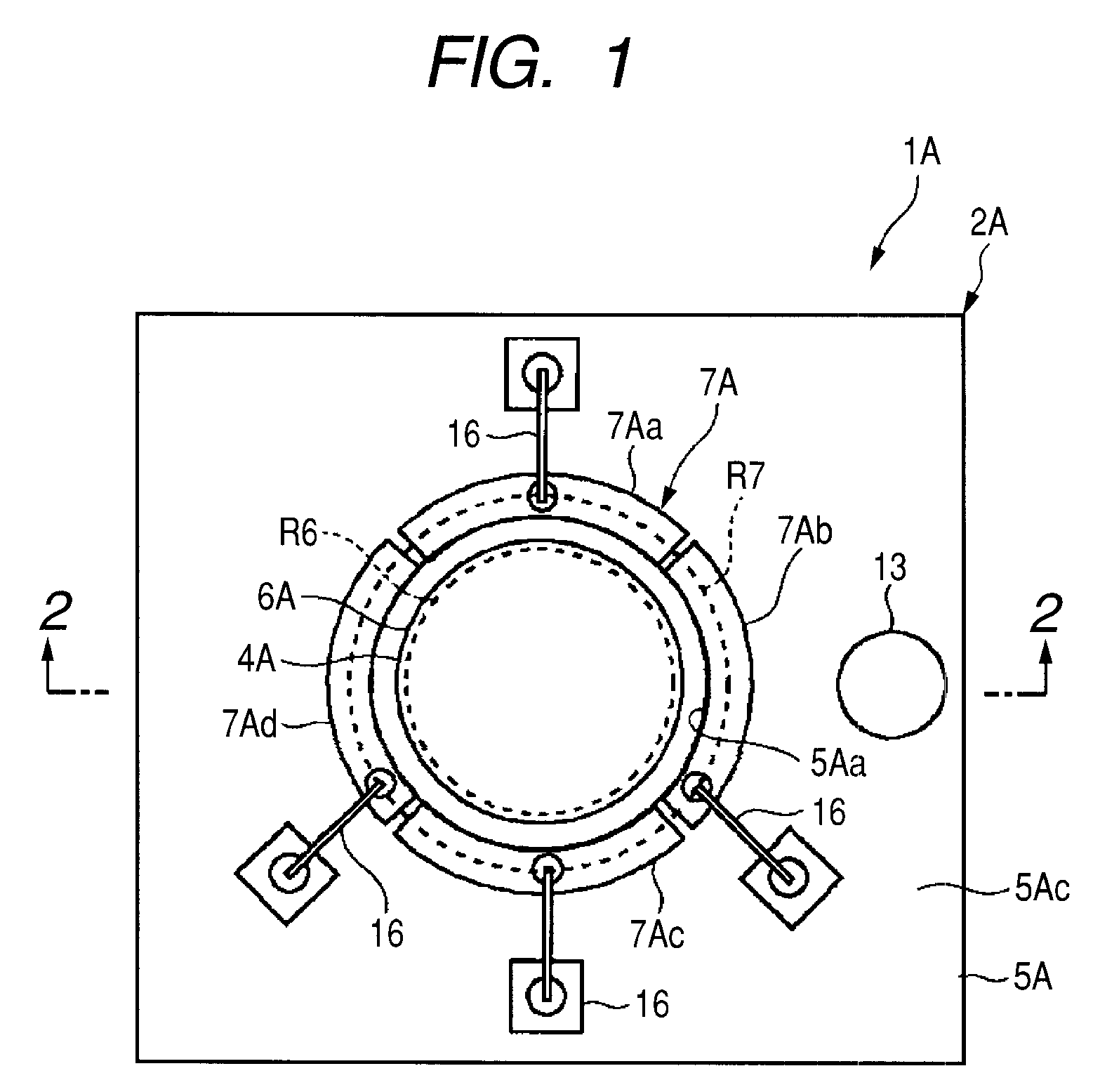
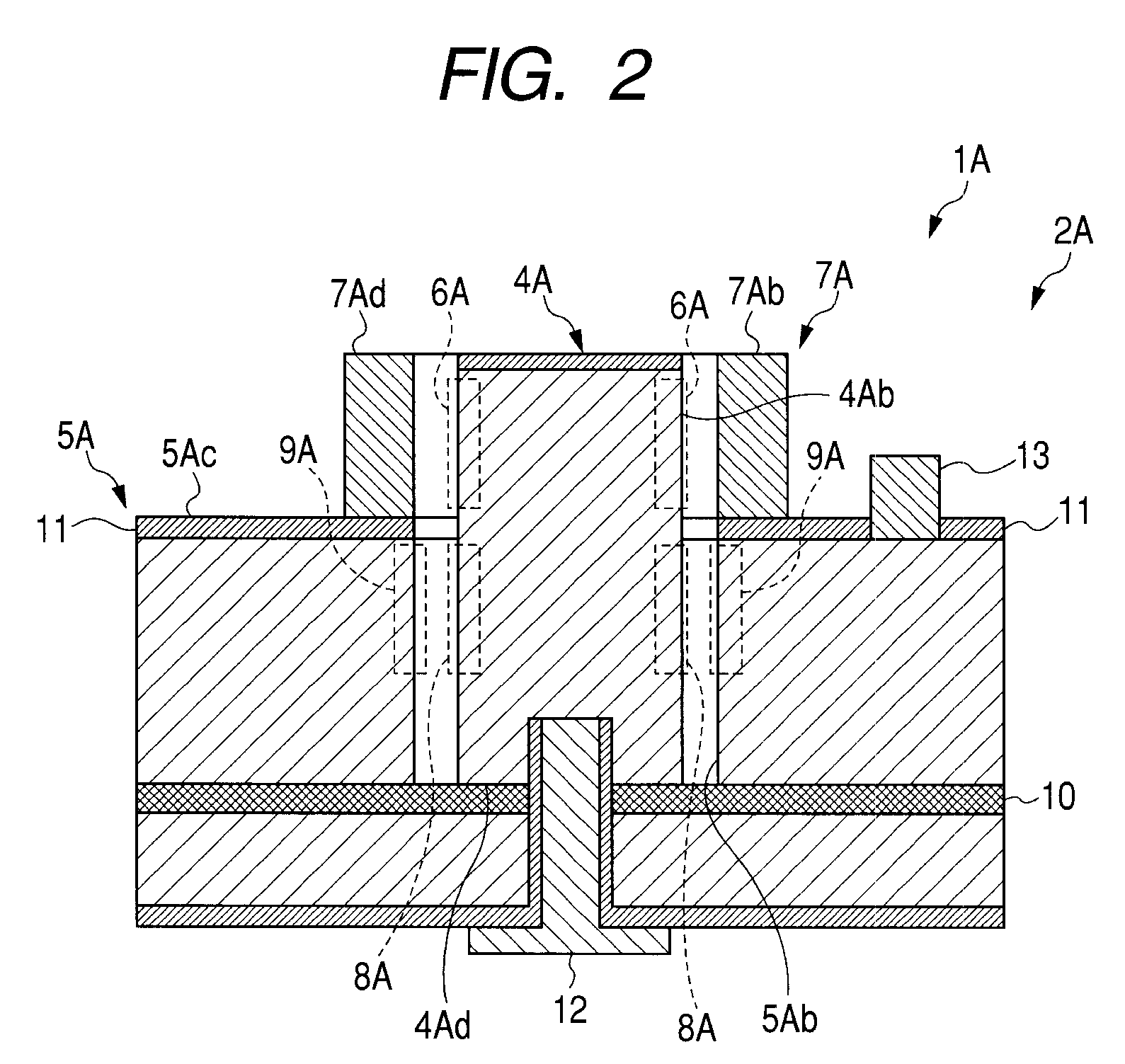
[0073]The variable capacitance device 1A includes the variable capacitance element 2A and an external power supply 3. In addition, as shown in FIGS. 1 and 2, the variable capacitance element 2A includes a columnar vibrator 4A, a supporting wall 5A, a first driving electrode 6A, a second driving electrode 7A (divided pieces are referred to as 7Aa, 7Ab, 7Ac, and 7Ad, respectively), a first capacitive electrode 8A, a second capacitive electrode 9A, and extended electrodes as constituent components.
[0074]The columnar vibrator 4A is formed in a cylindrical shape and stands upward from a surface (insulating surface) of an insulating layer 10, as shown in FIGS. 1 and 2. A single crystal silicon is selected as a material used for the columnar vibrator 4A from the point of view of how easily the columnar vibrator 4A can be formed and how precisely the columnar vibrator 4A can be formed. The columnar vibrator 4A is formed integrally with the insulating layer 10 using an insulator of an SOI (...
second embodiment
[0107]As shown in FIGS. 11 and 12, the variable capacitance element 2B includes a columnar vibrator 4B, a supporting wall 5B, a first driving electrode 6B, a second driving electrode 7B, a first capacitive electrode 8B, a second capacitive electrode 9B, and extended electrodes (a first driving electrode 6B, a second driving electrode 7B, a first capacitive electrode 8B, and a second capacitive electrode 9B) for the electrodes.
[0108]As shown in FIGS. 11 and 12, the columnar vibrator 4B is formed in a cylindrical shape and stands upward from a surface (insulating surface) of an insulating layer 10, in the same manner as the columnar vibrator 4A in the first embodiment. In addition, the columnar vibrator 4B has an insulating surface layer 11, which is formed on a top surface thereof by oxidation, in order to support the first driving electrode 6B positioned above the columnar vibrator 4B while maintaining an insulation property. A material used for the columnar vibrator 4B is the same...
third embodiment
[0137]Next, operations of the variable capacitance device 1C and the variable capacitance element 2C will be described with reference to FIGS. 15 to 16.
[0138]The variable capacitance device 1C according to the third embodiment includes the variable capacitance element 2C shown in FIG. 16 and the external power supply 3 (not shown). In the same manner as in the first embodiment, when four driving voltages (see FIGS. 4A to 4E) having a sinusoidal wave and a phase difference of 90° are sequentially applied from the external power supply 3 to the divided parts 7Ca to 7Cd of the second driving electrode 7C in the circumferential direction (direction of the part 7Ca->part 7Cb->part 7Cc->part 7Cd or an opposite direction) thereof while shifting the driving voltage by 90°, a driving voltage between the first driving electrode 6C and the second driving electrode 7C sequentially increases or decreases in the circumferential direction of the second driving electrode 7C. As a result, an electr...
PUM
 Abstract
Description
Claims
Application Information
 - Generate Ideas
- Intellectual Property
- Life Sciences
- Materials
- Tech Scout
- Unparalleled Data Quality
- Higher Quality Content
- 60% Fewer Hallucinations
Browse by: Latest US Patents, China's latest patents, Technical Efficacy Thesaurus, Application Domain, Technology Topic, Popular Technical Reports.
© 2025 PatSnap. All rights reserved.Legal|Privacy policy|Modern Slavery Act Transparency Statement|Sitemap|About US| Contact US: help@patsnap.com