Magnetic field concentrator for electromagnetic forming

a magnetic field and concentrator technology, applied in the direction of hose connections, mechanical devices, pipe elements, etc., can solve the problems of significant cost, the need to repair the joint of the weld formed as many as three times, etc., and achieve the effect of quick and easy exchange and cost reduction

Active Publication Date: 2009-04-07
THE BOEING CO
View PDF45 Cites 270 Cited by
  • Summary
  • Abstract
  • Description
  • Claims
  • Application Information

AI Technical Summary

Benefits of technology

[0010]The embodiments of the present invention provide several advantages. One such advantage is the provision of an economical technique to utilize a fixed electromagnetic coil and a fixed magnetic field concentrator with interchangeable inserts to allow production of a wide variety of tube and ferrule diameters. The field concentrator features a large internal diameter, into which a split cylindrical concentrator insert is placed to accommodate a specific tube and end fitting shape. Different concentrator inserts can quickly and easily be exchanged to alter production set-up to a different size tube and fitting.
[0011]The use of a concentrator in combination with an insert, as described herein, reduces costs by allowing one to change over a small relatively lightweight insert while maintaining a common fixed concentrator.

Problems solved by technology

A weld formed joint may need to be repaired as many as three times, at significant costs.

Method used


Image

  • Magnetic field concentrator for electromagnetic forming
  • Magnetic field concentrator for electromagnetic forming
  • Magnetic field concentrator for electromagnetic forming

Examples


Embodiment Construction

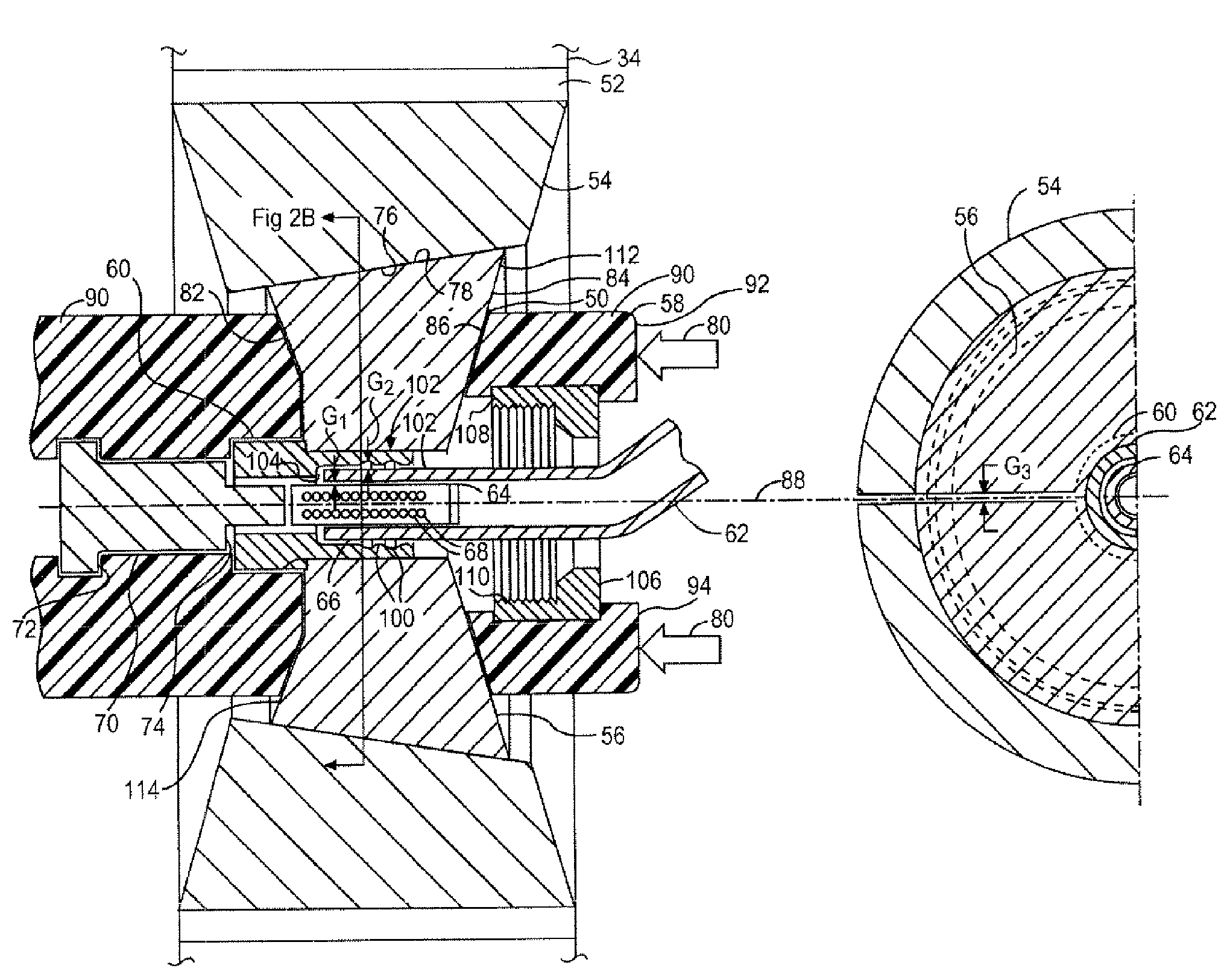
[0030]In each of the following Figures, the same reference numerals are used to refer to the same components. While the present invention is described with respect to a system for magnetically forming a fluid joint and to the joints formed therefrom, the present invention may be adapted for various applications, such as air, liquid, and fluid applications. The present invention may be applied to both low-pressure applications, i.e. less than approximately 2500 psi, and high-pressure applications of greater than approximately 5000 psi, as well as to applications therebetween. The present invention may be applied to fluid applications in the aerospace, automotive, railway, and nautical or watercraft industries, as well as to other industries where fluid tight joints are utilized, such as residential or commercial plumbing.

[0031]In the following description, various operating parameters and components are described for one constructed embodiment. These specific parameters and component...


PUM

PropertyMeasurementUnit
pressureaaaaaaaaaa
pressureaaaaaaaaaa
widthaaaaaaaaaa

Abstract

A magnetic forming system (10) for creating a fluid circuit joint between a tube and a fitting includes an induction coil (12). The induction coil (12) may form a first stage electromagnetic current. A field concentrator (132) may focus the first stage electromagnetic current to form a second stage electromagnetic current. An insert (136) may focus the second stage electromagnetic current to form an electromagnetic field. The electromagnetic field forms the fluid circuit joint. The induction coil (12) may be insertable within the tube, generate an electromagnetic field, and impose the electromagnetic field on and to expand a portion of the tube within the fitting to form the fluid circuit joint. The system (10) may include a receptacle (54) that is external to the tube and the fitting. An insert (56) may be mechanically coupled within the receptacle (54) and limit the outward expansion of the tube and the fitting.

Description

RELATED APPLICATION[0001]The present invention is related to U.S. patent application Ser. No. 11 / 028,093 entitled “Electromagnetic Mechanical Pulse Forming of Fluid Joints for Low-Pressure Applications”, U.S. patent application Ser. No. 11 / 865,452 entitled “Electromagnetic Pulse Welding of Fluid Joints”, and U.S. patent application Ser. No. 10 / 905,211 entitled “Electromagnetic Mechanical Pulse Forming of Fluid Joints for High-Pressure Applications”, which are incorporated by reference herein.TECHNICAL FIELD[0002]The present invention generally relates to the solid state coupling of metallic tubes and fittings. More specifically, the present invention is related to the systems and components utilized in the magnetic coupling of the tubes to the fittings.BACKGROUND ART[0003]Metallic tubes are commonly used to carry fluid in the form of gas or liquid throughout various fluid circuits in many industries. This is especially true in the aerospace industry, due to the lightweight and stron...

Claims


Application Information

Patent Timeline
Patent Type & Authority Patents(United States)
IPC IPC(8): B23P17/00F16L55/00
CPCB21D26/14F16L13/0281F16L19/0206F16L13/141Y10T29/49803
Inventor FISCHER, ALLEN
Owner THE BOEING CO
Why Eureka
Try Eureka