Method and arrangement for a sewing machine

a sewing machine and arrangement technology, applied in the field of arrangement and a method of sewing machines, can solve the problems of increasing the maximum speed and acceleration of thread, increasing the stroke length of thread tensioning and take-up levers, time-consuming and awkward, etc., and achieves the effect of not limiting the invention, increasing the size of the lower bobbin, and not affecting the sewing work

Active Publication Date: 2009-04-07
SINGER SOURCING LTD LLC
View PDF10 Cites 3 Cited by
  • Summary
  • Abstract
  • Description
  • Claims
  • Application Information

AI Technical Summary

Benefits of technology

[0022]A significant advantage of the invention is that the size of the lower bobbin can be increased. This can thereby store a greater quantity of lower thread, so that the lower thread needs to be replenished less often, an operation which is very disruptive in sewing work.
[0023]The thread feeder may comprise a thread apportioning mechanism of the type described below. However, any arrangement which apportions the upper thread may be used in the invention. This is therefore feasible with a motor, such as a stepping motor, which drives rollers, between which the thread is clamped and advanced. Another variant may consist of magnets, which cyclically clamp the upper thread between two plates, which are driven by the magnets to repeatedly move the plates in the longitudinal direction of the thread whilst they are clamped together.
[0024]The sewing machine control element comprises a processor, which gathers information on parameters set by the sewing machine operator and by data on the current positions of mechanical elements relevant for correct execution of a selected seam, and which controls the sewing of the sewing machine using these parameters and current positions as a basis. Such control is known and does not form part of the invention, so that it will not be described here.
[0025]The control element controls the drive element for the thread feeder, for example said motor, where the drive element is used for undertaking an adjustment of the upper thread consumption per stitch, calculated in the processor, and the excess thread described.
[0026]Further characteristics of the present invention are demonstrated in the following detailed description, which is to be interpreted in association with the drawings attached. It must be emphasized that the drawings are given solely for the purpose of illustration and do not limit the invention. The drawings are not drawn to scale and only show the underlying concept of structures and procedures described herein.

Problems solved by technology

One of the limitations inherent in the prior art is that the bobbin for the lower thread has a limited storage capacity for the lower thread, so that this lower bobbin has to be changed fairly frequently for a lower bobbin filled with lower thread, This is time-consuming and awkward.
For reasons of space, however, an increased stroke length of the thread tensioning and take-up lever is not desirable.
It is furthermore desirable to avoid larger mechanical movements which, among other things, result in an increase in the maximum speed and acceleration of the thread tensioning and take-up lever, which places greater stresses on the mechanical drive parts and increases the risk of vibrations in the sewing machine.
One disadvantage with the solution demonstrated is a considerably more complicated mechanism than hitherto used in sewing machines.

Method used


Image

  • Method and arrangement for a sewing machine
  • Method and arrangement for a sewing machine
  • Method and arrangement for a sewing machine

Examples


Embodiment Construction

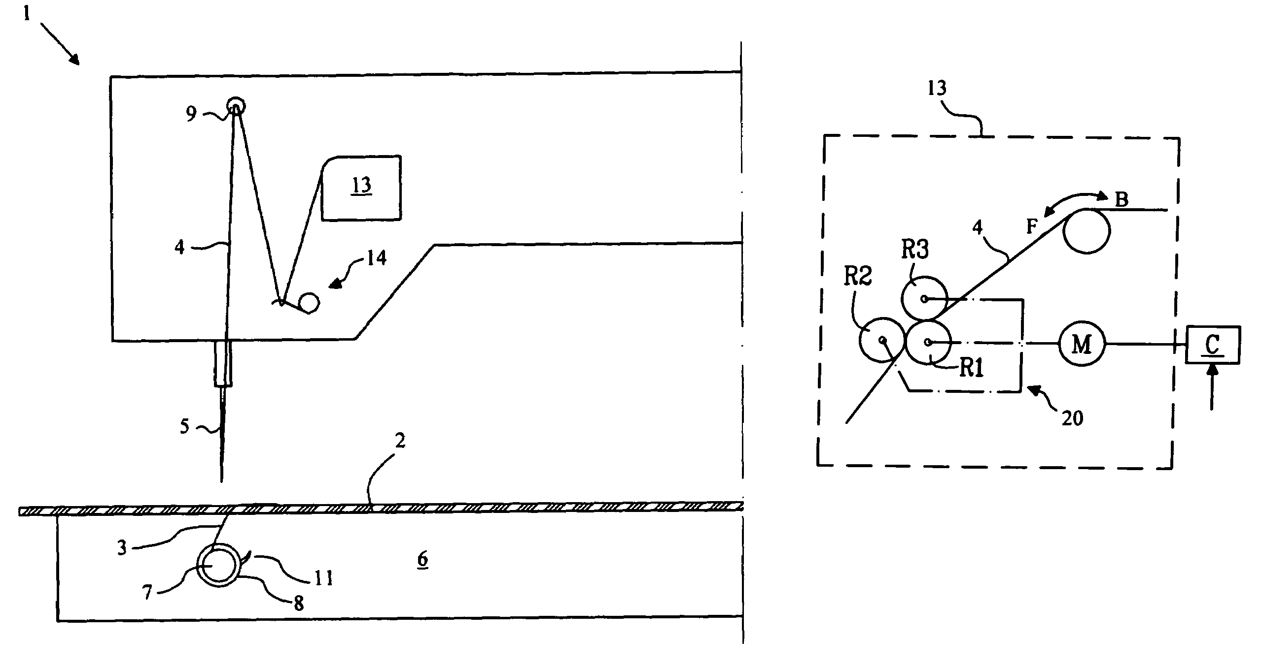
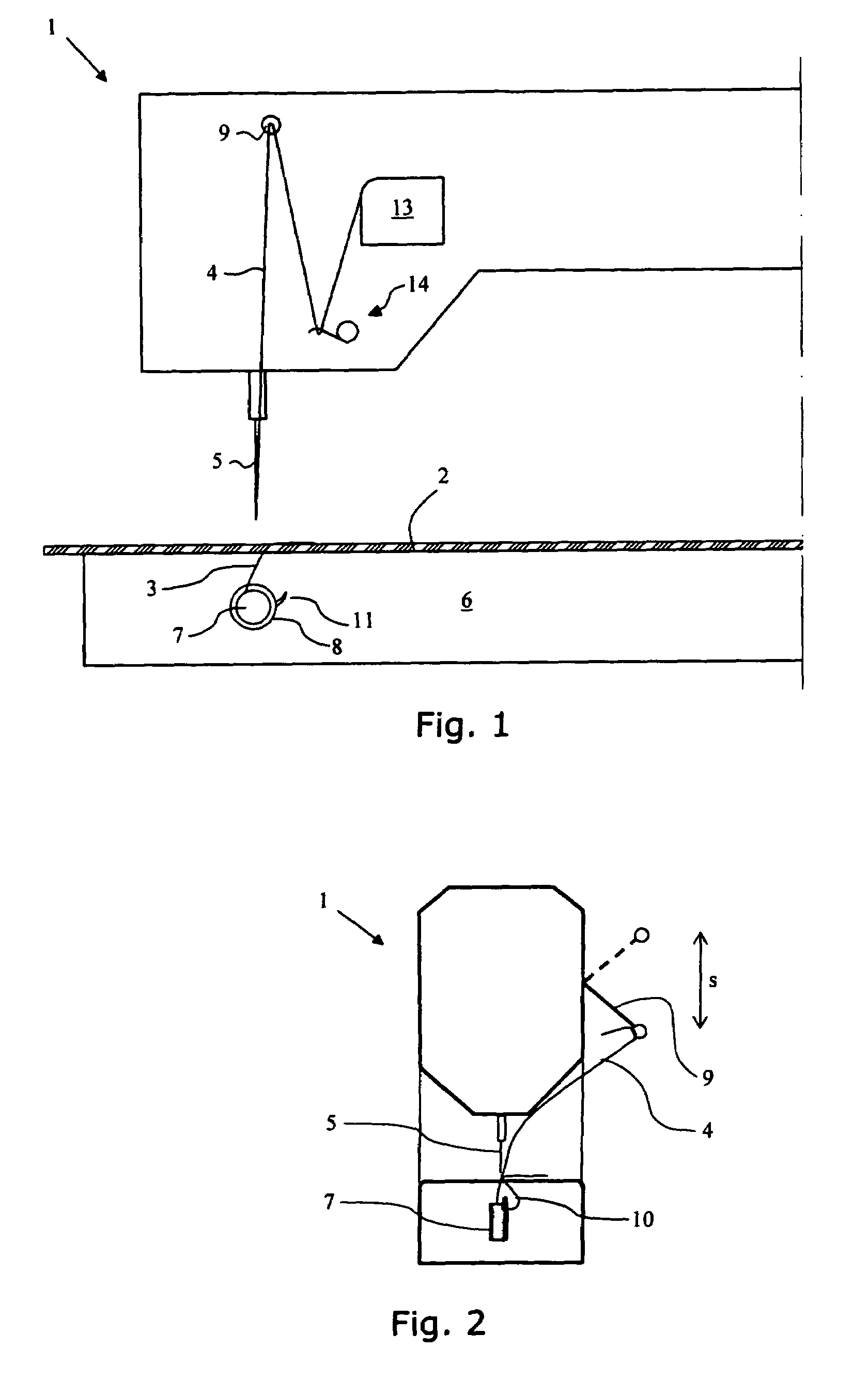
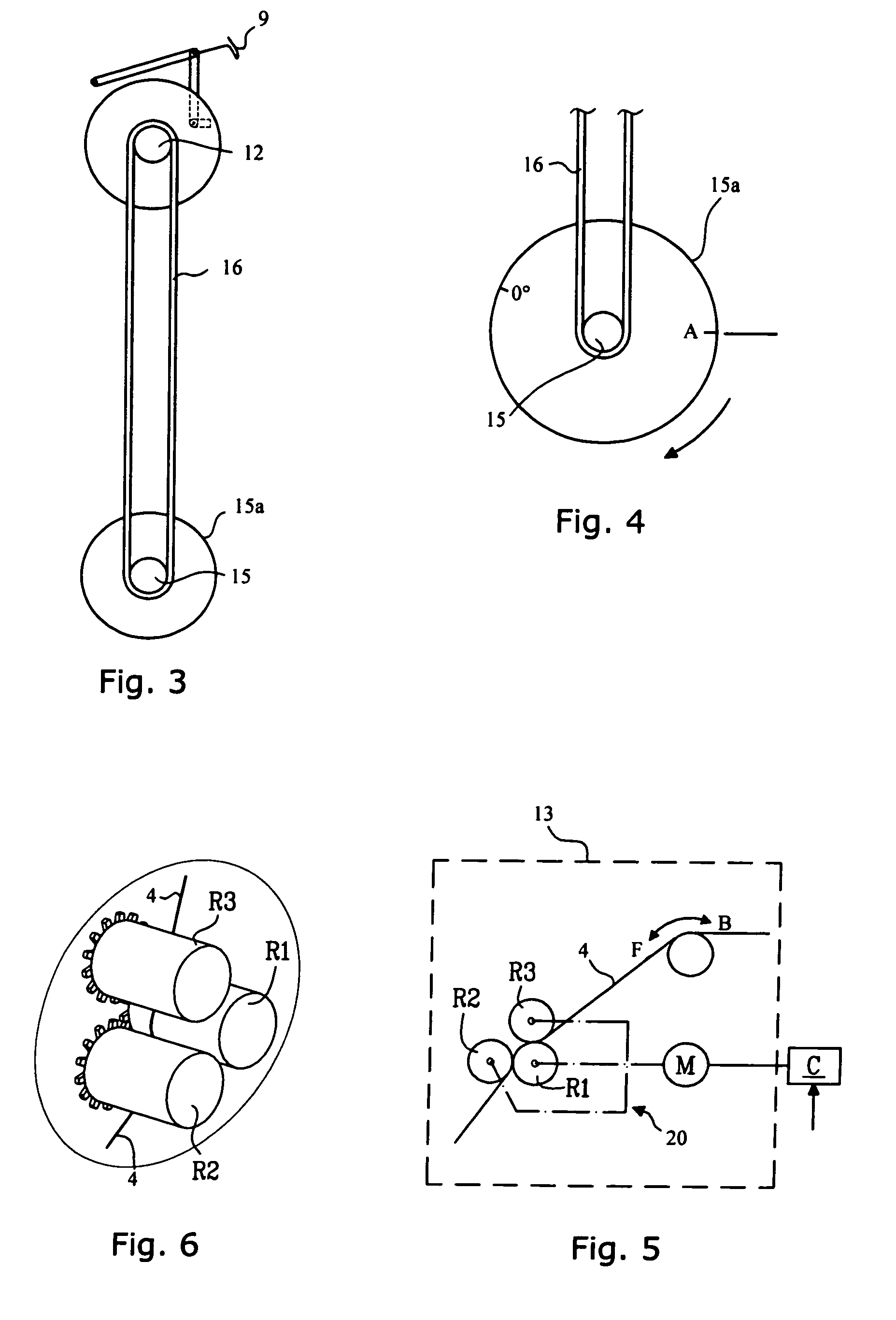
[0013]In the prior art the entire stroke length of the thread tensioning and take-up lever is utilised in order to produce a loop in the upper thread which has a circumference large enough to allow the upper thread to be carried around lower bobbin by the shuttle. The length of the thread loop is then basically twice the stroke length of the thread tensioning and take-up lever. According to the invention both a thread tensioning and take-up lever and a thread feeder are used in order to feed the upper thread to the needle. Such an arrangement means that one is not dependent on the stroke length of the thread tensioning and take-up lever to produce the required size of the upper thread loop, which is needed in order to allow the upper thread to be carried around the lower bobbin. By means of a control element in the sewing machine, which controls the thread feeder, the required length of thread can be fed during a stitch, following which the thread length at the end of the stitch can...


PUM


Abstract

A sewing machine including a needle that is supplied with an upper thread. A a reciprocating movement carries the upper thread through a sewing material and forms a loop beneath the sewing material. A shuttle houses a bobbin for lower thread and a shuttle arm catches the loop of the upper thread and carries the upper thread around the lower bobbin, so that a stitch is executed on the sewing material. A thread feeder feeds the upper thread to the needle and a control element on each stitch causes the thread feeder at the beginning of a stitch to advance a predetermined length of upper thread, including an excess thread, and at the end of the stitch to correct the length of the upper thread by recovering the excess upper thread, or advancing the further upper thread required.

Description

CROSS-REFERENCE TO RELATED APPLICATIONS[0001]This application claims priority to Swedish patent application 0501248-9 filed Jun. 1, 2005.TECHNICAL FIELD[0002]The present invention relates to an arrangement and a method for a sewing machine. In particular the invention demonstrates a method and an arrangement for improving access to the upper thread in the formation of a stitch, which in turn permits an increase in the volume of a bobbin which stores the lower thread, so that this bobbin does not need to be changed as frequently as in hitherto known sewing machines of corresponding type.PRIOR ART[0003]Sewing machines of the lockstitch type have long been known in the art and their operating principle is well-known. If, for the sake of simplicity, a sewing machine with a single needle is taken as an example, the stitches in this machine are formed in that an upper thread and a lower thread are knotted together be means of a needle, which moves with a reciprocating motion through a sew...

Claims


Application Information

Patent Timeline
Patent Type & Authority Patents(United States)
IPC IPC(8): D05B45/00D05B47/00
CPCD05B49/00
Inventor EKLUND, HENRIK
Owner SINGER SOURCING LTD LLC
Why Eureka
Try Eureka