Movable ballast in a sailing vessel

a sailing yacht and ballast technology, applied in the field of sailing yachts, can solve the problems of increasing drag, increasing weight, and reducing the effective area of the lifting surface of the keel, so as to reduce the angle of the heel center, increase drag, and increase weight

Active Publication Date: 2009-04-07
MORRIS MATTHEW G
View PDF8 Cites 2 Cited by
  • Summary
  • Abstract
  • Description
  • Claims
  • Application Information

AI Technical Summary

Benefits of technology

[0009]Attempts to reduce the angle of heel center on moving ballast. Two typical methods of moving ballast to the windward side of the vessel include: the swing keel and internal water ballast. This invention differs from prior art in several ways. The examples cited above either add weight, increases drag, or reduces the effective area of the lifting surface of the keel. This invention maintains the vertical orientation of the keel to the hull as a lifting surface and does not add weight to the vessel to increase the righting moment.
[0010]Water ballast systems require pumps and a water source to pump water from one side of the hull to the other to increase the righting moment and decrease the angle of heel. Since the effectiveness of ballast is proportional to the distance of the ballast from the centerline of the vessel, and since water ballast by definition must be contained within bladders or tanks mounted inside the ship's hull, significantly more water weight is needed to generate the same amount of righting moment as ballast suspended from the ship's keel. Mounting water ballast tanks and associated plumbing in a ship uses significant space and the additional weight affects sailing performance in several ways. The additional weight increases the wetted area of the hull (the boat rides deeper than it would with less weight), increasing drag and reducing performance. Shifting large quantities of water requires complex plumbing and mechanical equipment, and can include sensors and controls. Failures in any of these components can reduce the ships ability to move water to the appropriate location, affecting the sailing performance and possibly affecting the safety of the vessel.
[0012]FIG. 1 shows the overall concept of the rotating externally ballasted keel. The center of mass of a ballast weight 12 is located aft of a shaft 14 which supports the load and allows the ballast to rotate. The support beam 14 for the ballast weight is also a hydrodynamic surface which, when rotated, provides righting moment together with the offset weight of the ballast 12. The ballast 12 also moves forward as it swings. This serves to maintain fore / aft hull trim. The concept allows for a simpler, more effective and more reliable implementation as compared to prior art.
[0013]In the preferred embodiment, the ballast 12 is cantilevered from a rotating shaft 14, no technical work is done to move the ballast 12 (the ballast is not lifted—but rotated), decreasing structural loads and mechanism complexity. This approach eliminates the need for the complex hydraulics required for swing keels and allowing the device to be manipulated by hand in smaller vessels or by electric motor in larger vessels. Rotating seals on the shaft are much more reliable and easy to implement than sealing the hinged area between a swing keel and hull. In this approach, even if the seals failed, the opening in the hull for the shaft could be made above the waterline, which would not allow water to enter the vessel—even if the seal completely failed, a safer approach. This design also provides for a clean transition from the hull to the keel as compared to the flexible interface in a swing keel design, thereby avoiding the increase in drag associated with that flexible seal approach.

Problems solved by technology

The examples cited above either add weight, increases drag, or reduces the effective area of the lifting surface of the keel.
Mounting water ballast tanks and associated plumbing in a ship uses significant space and the additional weight affects sailing performance in several ways.
Shifting large quantities of water requires complex plumbing and mechanical equipment, and can include sensors and controls.
Failures in any of these components can reduce the ships ability to move water to the appropriate location, affecting the sailing performance and possibly affecting the safety of the vessel.
Because of the cost and complexity of this approach, most vessels employing this design are built for sailing competition.
The swing keel approach adds no additional ballast weight, but swinging the keel away from the centerline of the boat has several adverse affects.
First, swinging the keel away from a perpendicular presentation reduces the aspect of the keel, allowing more leeway when sailing upwind.
In addition, if any component in the system fails, the vessel would become unsafe and forced to retire from competition.

Method used


Image

  • Movable ballast in a sailing vessel
  • Movable ballast in a sailing vessel
  • Movable ballast in a sailing vessel

Examples


Embodiment Construction

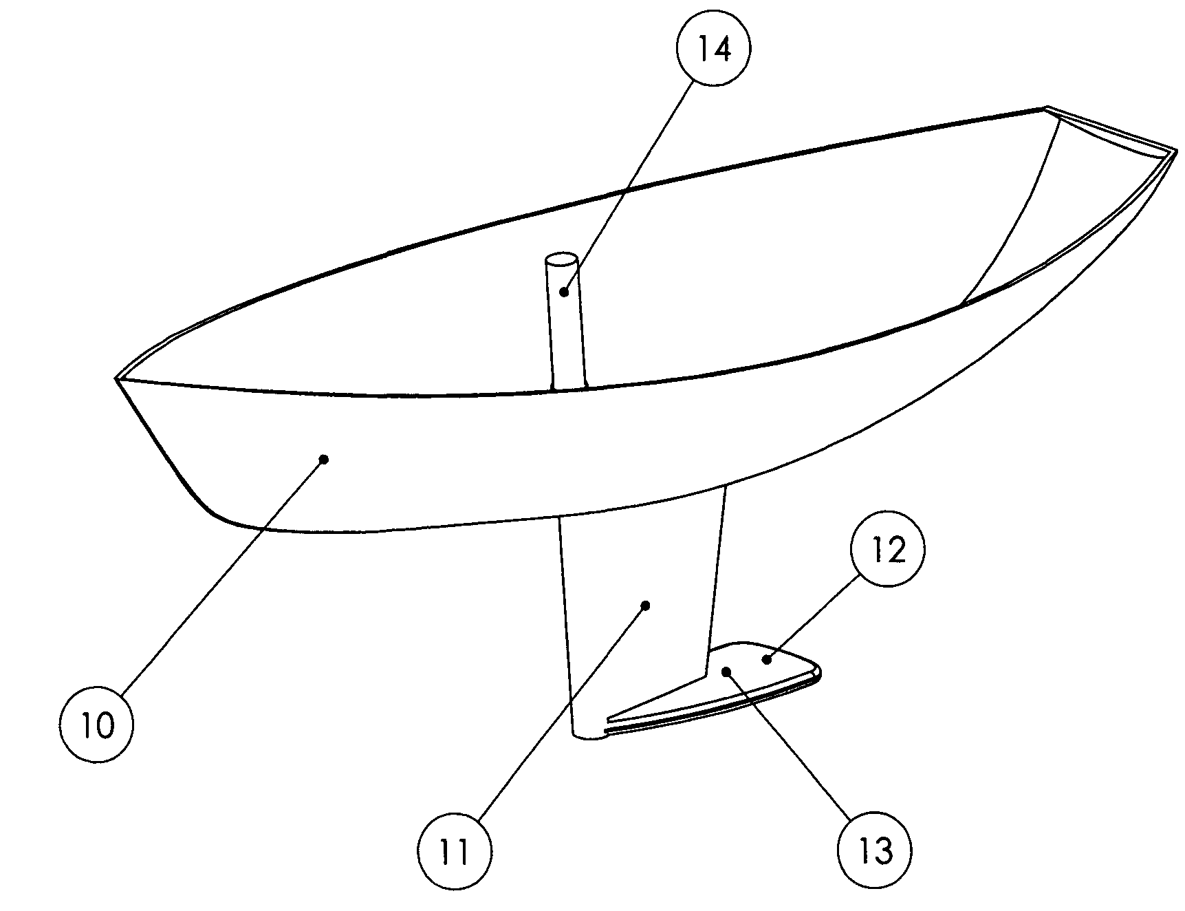
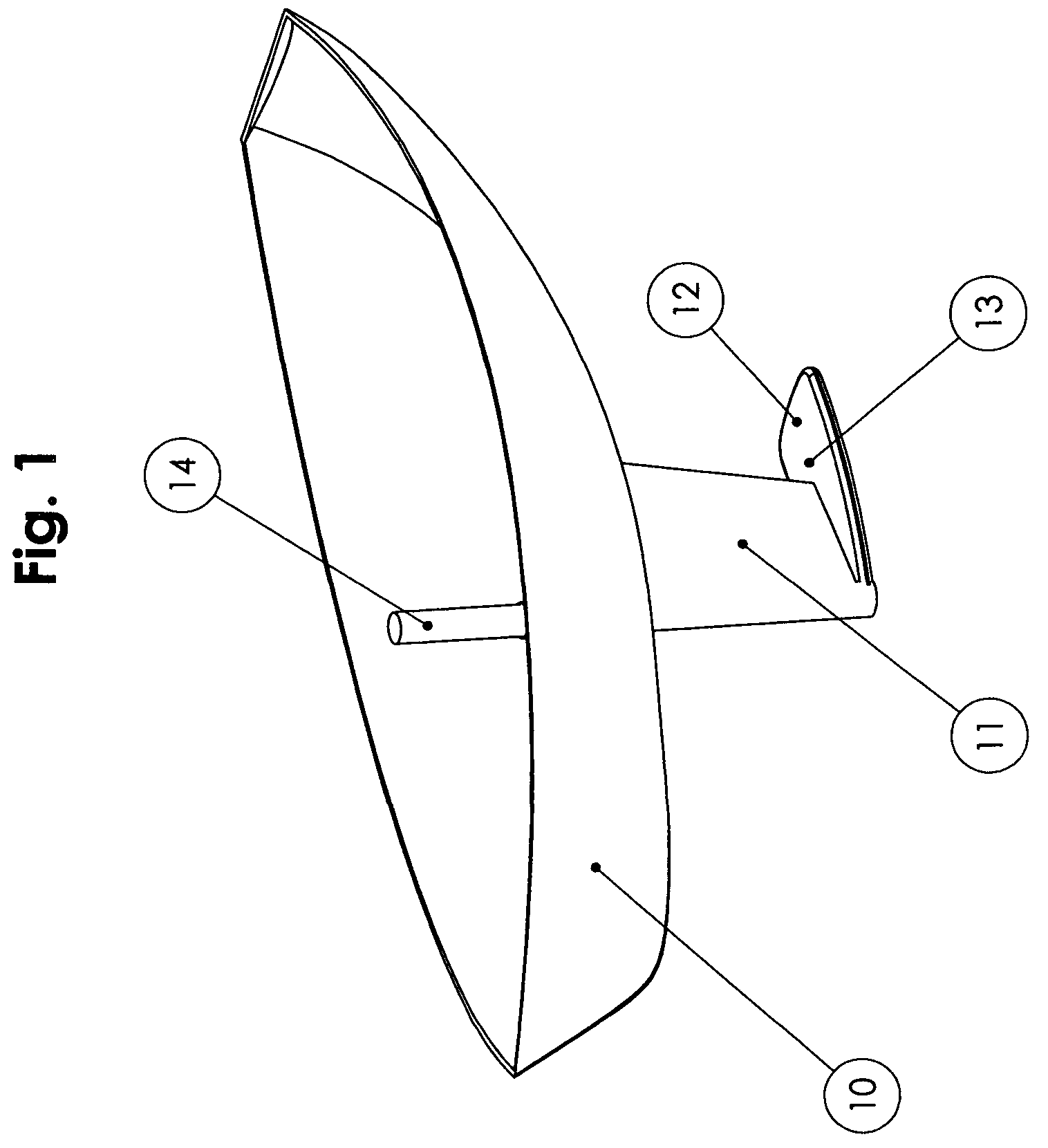
[0025]FIG. 1 shows a typical hull 10 with fixed keel 11, support beam 13 and ballast 12. Said ballast 12 is mounted to shaft 14 which is mounted and supported in the forward portion of fixed keel 11. Rotating shaft 14 rotates the ballast 12 away from the centerline of the vessel. The connection and ballast support beam 13 on the bottom of said keel 11 can be arranged so that the center of mass of the ballast 12 moves forward and the support beam 13 angles down when shaft 14 is rotated.

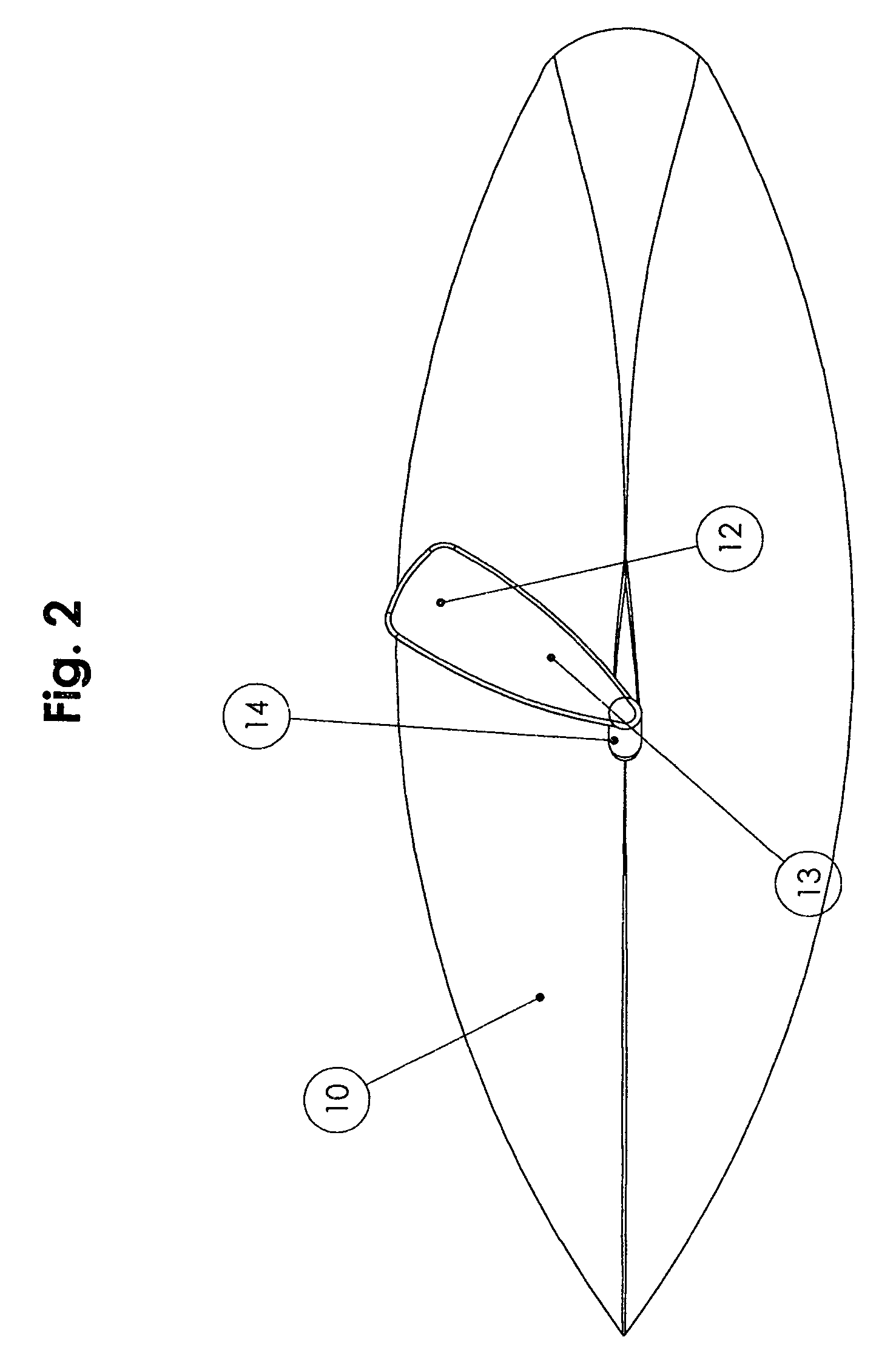
[0026]FIG. 2 shows the location of the center of mass of ballast 12 with respect to the centerline of the vessel 10 as it is rotated about shaft 14. In this view, ballast 12 is positioned for sailing upwind on port tack. Righting moment is increased by both the movement of the center of mass of ballast 12 away from vessel 10 centerline and by the downward angle of attack of support beam 13.

[0027]FIG. 3 shows the vessel moving in the direction of the wind. For this running condition, the center of mass ...


PUM


Abstract

An external adjustable ballast system for keeled sailboats comprising a weight that is designed for low hydrodynamic drag, mounted through a beam to a shaft running down the leading edge of the fin keel. Turning the shaft moves the weight to optimize hull trim, both fore / aft and athwartships, for a particular point of sail. If the weight and beam are shaped as a lifting body and mounted to the shaft such that it pivots as it rotates to optimize angle of attack, the dynamic balancing component can allow for a lighter weight. Ballast weight and beam can be raised or lowered to optimize performance for expected wind conditions. The leading edge of the fin keel is a rotatable non spherical shaft. When rotated, the shaft creates an asymmetric cross section which improves hydrodynamic efficiency of the keel.

Description

BACKGROUND OF THE INVENTION[0001]1. Technical Field[0002]This invention relates generally to sailing yachts, and more particularly to externally ballasted high performance sailing yachts.[0003]2. Description of Related Art[0004]Typically, external ballast is located at the lowest point on rigidly fixed keels. The keel serves two functions—it supports the external ballast and it provides a high aspect lifting surface to keep the vessel from sliding sideways as it sails upwind. As the vessel heels, the ballast works to counteract the force of the wind. There is no restoring force until some angle of heel is generated. As vessels heel, the effective area of the lifting surface reduces, comprising the windward performance. Attempts to reduce the angle of heel, center on moving ballast. Two typical methods of moving ballast to the windward side of the vessel include the swing keel and internal water ballast. The swing keel mounts ballast on the bottom of the keel, using the keel as a mom...

Claims


Application Information

Patent Timeline
Patent Type & Authority Patents(United States)
IPC IPC(8): B63B35/00
CPCB63B41/00B63B2041/003
Inventor MORRIS, III, MATTHEW G.MORRIS, JR., MATTHEW G.
Owner MORRIS MATTHEW G
Why Eureka
Try Eureka