
Canister heater

Inactive Publication Date: 2009-04-07
INERGY AUTOMOTIVE SYST RES (SA)
View PDF19 Cites 7 Cited by
  • Summary
  • Abstract
  • Description
  • Claims
  • Application Information

AI Technical Summary

Benefits of technology

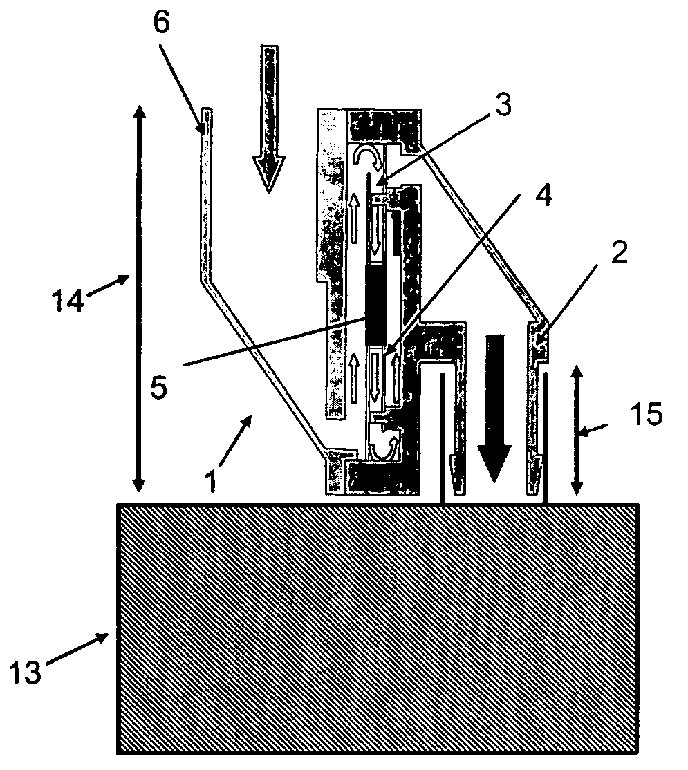
[0009]To alleviate the abovementioned drawbacks, the object of the present invention is therefore to provide a heater for heating the purge air before it passes through the canister, while still introducing no or little additional pressure drop and offering a geometry that ensures the heater can be used on canisters with different geometries.
[0010]The heater also makes it possible to add an additional functionality—the heating of the purge air—to a standard canister that does not possess this functionality.
[0031]The heating elements are preferably resistance heating elements, in particular of the PTC type. They consist of ceramic blocks, the electrical resistance of which suddenly increases at a given temperature. This has the effect of limiting the electrical current flowing in the resistance elements, and therefore of preventing overheating.
[0038]Preferably, the heater further includes a spacer housed in the casing and at least partly separating the electronic controller from the plates. The spacer makes it possible to protect the controller from the heat radiated by the plates. It is generally provided with ribs which locally reinforce the spacer and give it the strength needed to resist any load to which it is subjected inside the casing.

Problems solved by technology

Fuel leaks due to lack of sealing and also losses by evaporation are most particularly the subject of increasingly stringent regulations, especially for applications in motor vehicles.
A major problem with systems for controlling evaporative loss using activated charcoal as adsorbent material in the canister is that, under low ambient temperature conditions, it is difficult for the fuel that has been adsorbed to be released and purged from the canister.
When the temperatures drop well below the ambient temperature, the effectiveness of the system is significantly impaired.
Such a canister has the drawback of heating the adsorbent and not the air flowing when the main canister is being purged and, in addition, the drawback of introducing additional pressure drops in the flow of purge air.

Method used


Image

  • Canister heater
  • Canister heater
  • Canister heater

Examples


Embodiment Construction

[0057]Referring now to the drawings, wherein like reference numerals designate identical or corresponding parts throughout the several views.

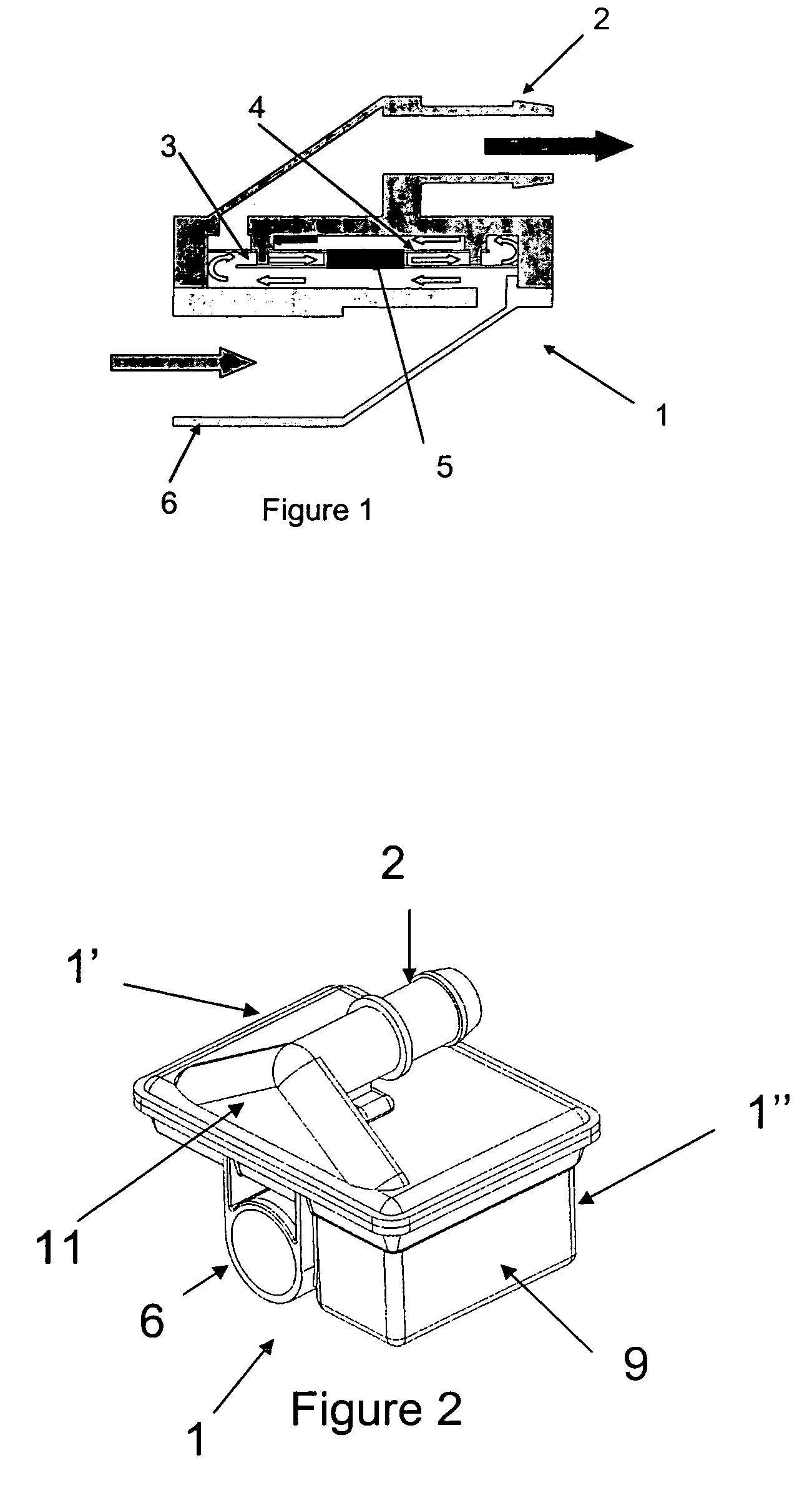
[0058]FIG. 1 illustrates schematically a heater comprising a casing (1) provided with two couplers (2) and (6), the coupler (2) of which is intended to be connected to the venting outlet of a canister and the coupler (6) is intended to be connected to an OBD device. The purge air flows through the heater, between the plates (3) and (4), in the direction of flow indicated by the arrows. A heating element (5) is inserted between the plates (3) and (4).

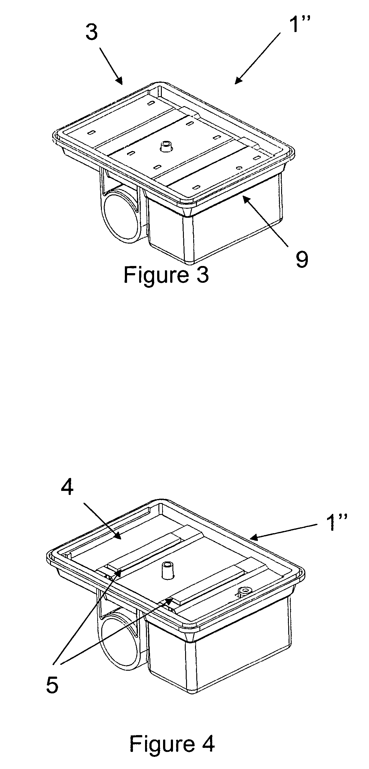
[0059]FIGS. 2 to 6 show various views of one possible embodiment of the heater according to the invention.

[0060]The casing (1) in FIG. 2 comprises two parts (1′) and (1″) that are provided with respective couplers (2) and (6). Furthermore, the part (1″) of the casing (1) includes a housing (9) for an electronic controller (not shown).

[0061]In FIG. 3, the part (1′) has been omitted so as to show only...


PUM


Abstract

A heater for heating a fluid intended to pass through a fuel tank canister is provided. The heater includes a casing provided with a coupler for coupling to the canisters, at least two plates placed inside the casing in substantially parallel planes, and at least one heating element housed between the plates. The at least two plates are place inside the casing such that the fluid flows between the two plates. The coupler is placed in a plane substantially parallel to at least one plane of one of the plates and the projected area of the coupler on the plane of one of the plates lies substantially within the projected area of the casing on the plane.

Description

BACKGROUND OF THE INVENTION[0001]1. Field of the Invention[0002]The present invention relates to a heater for heating a fluid intended to pass through a fuel tank canister.[0003]2. Description of the Related Art[0004]Fuel vapours escaping from a fuel system are a source of hydrocarbon emissions in motor vehicles. Fuel leaks due to lack of sealing and also losses by evaporation are most particularly the subject of increasingly stringent regulations, especially for applications in motor vehicles.[0005]Now, fuel tanks, in particular for motor vehicles, usually have a venting orifice for balancing the internal pressure with the atmospheric pressure, for example during variations in the fuel level resulting from filling the tank or from the consumption of fuel by the engine, or else during variations in temperature. Therefore, to meet the aforementioned standards, this venting orifice is conventionally connected to atmosphere via a duct and a chamber, usually called a canister, which con...

Claims


Application Information

Patent Timeline
IPC IPC(8): F02M33/02
CPCF02M25/0854F02M31/13F24H3/0405F02M2025/0881Y02T10/126Y02T10/12
Inventor POTIER, VINCENT
Owner INERGY AUTOMOTIVE SYST RES (SA)
Learn More