Air lock cover vent for telecommunications equipment

a technology for air lock cover and telecommunications equipment, which is applied in the direction of electric cable installation, cable installation in the cable chamber, packaging, etc., can solve the problems of telecommunications equipment being submerged in water, damage or destruction of equipment, and ultimately damage or destruction

Inactive Publication Date: 2009-04-07
INTEL CORP
View PDF38 Cites 16 Cited by
  • Summary
  • Abstract
  • Description
  • Claims
  • Application Information

AI Technical Summary

Benefits of technology

[0008]The present invention is directed to an improved vault or cabinet for subterranean storage of electronic equipment, such as wireless telecommunications equipment. In a particularly innovative aspect of the invention, the cabinet includes an air tight inner enclosure forming an air lock over and around the electronic equipment to prevent water from rising within the inner enclosure and submerging the electronic equipment as the cabinet floods. In a preferred embodiment, the cabinet further comprises an air guide interposed between the inner enclosure and the electronic equipment to aid in directing air flow up and over the electronic equipment. Preferably, the air guide includes a plurality of perforations or apertures that aid in heat transfer of the heat generated by the electronic equipment.

Problems solved by technology

In many municipalities the planning departments are unwilling to grant permit applications for unsightly tower installations.
The problem with any self-contained, sealed underground vault is that the telecommunications equipment enclosed therein generates heat, which ultimately damages or destroys the equipment.
Moisture, either from evaporation or flooding from rain, can also damage or destroy the equipment.
However, in the case of flooding, if the pump is unable to keep up with incoming flow or water, the telecommunications equipment can become submerged in water and ultimately damaged or destroyed.

Method used


Image

  • Air lock cover vent for telecommunications equipment
  • Air lock cover vent for telecommunications equipment
  • Air lock cover vent for telecommunications equipment

Examples


Embodiment Construction

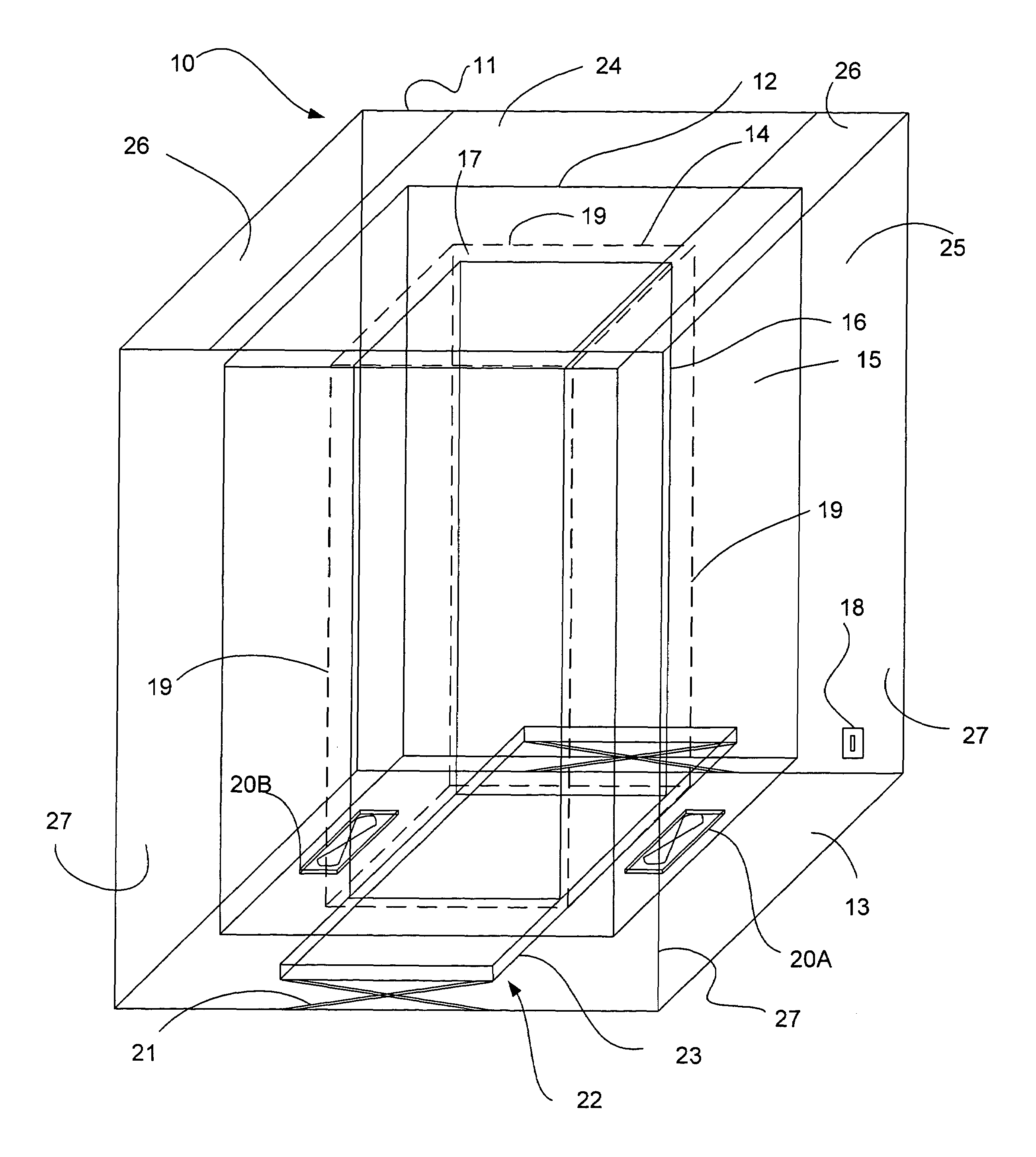
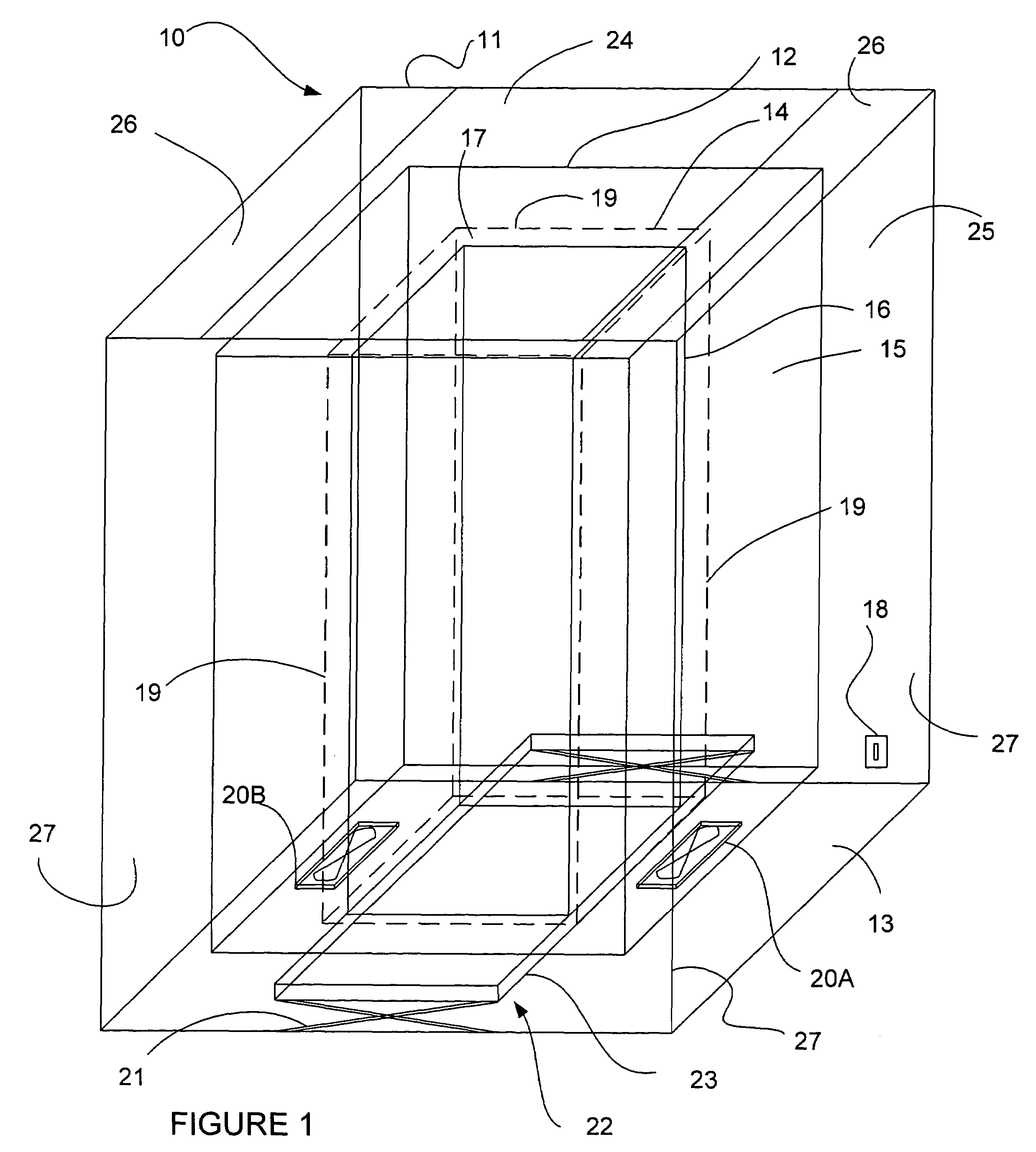
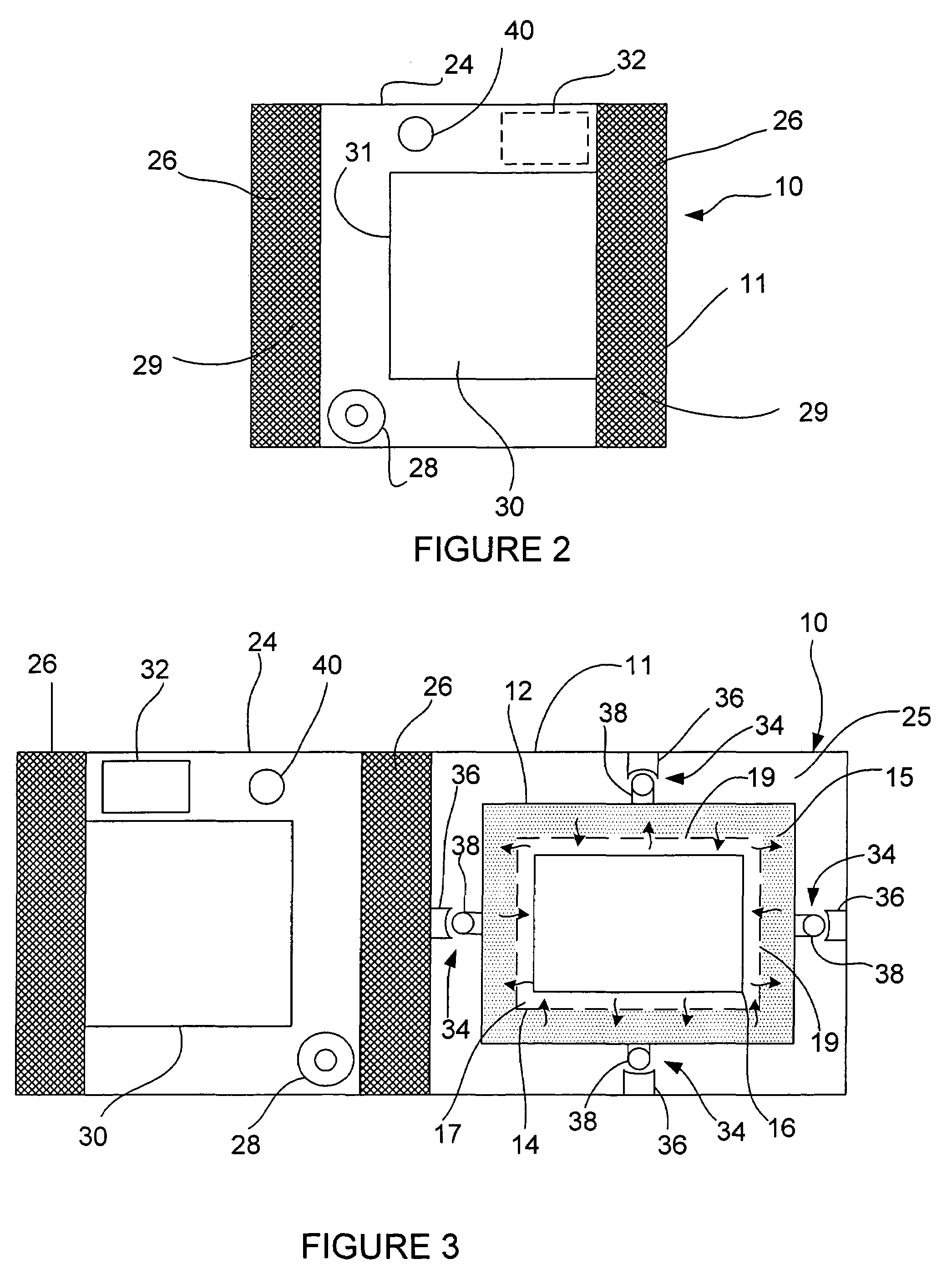
[0016]Referring to FIGS. 1-4, a cabinet or vault 10 for subterranean storage of electronic equipment is shown. The vault 10 includes an enclosure 11 that is preferably formed as a metal weldment. In a preferred embodiment, the enclosure 11 is a stainless steel weldment. Use of a metal, such as stainless steel, advantageously allows the surrounding earth to aid in the dissipation of heat from the vault 10 and, also, advantageously enables the vault 10 to be smaller, without sacrificing strength or equipment security. As a result, the vault 10 can advantageously be placed next to or under vertical structures, such as a light standard, in existing public rights of way.

[0017]Alternatively, the enclosure 11 may be formed of reinforced ultra violate inhibitent plastic injection molded material and may be made to any size necessary to accommodate the electronic equipment to be stored.

[0018]The enclosure 11 includes vertical walls 27 coupled to a bottom plate or base 13. A top plate or lid ...


PUM


Abstract

An improved vault that facilitates the underground storage of electronic equipment, such as instrumentation for wireless telecommunications antenna systems. The vault preferably includes an air lock cover that prevents the electronic equipment from being submerged under water when the vault floods.

Description

CROSS-REFERENCE TO RELATED APPLICATION[0001]This application claims the benefit of U.S. Provisional Application No. 60 / 483,488, filed Jun. 27, 2003, which application is incorporated herein by reference.FIELD OF THE INVENTION[0002]The present invention relates generally to subterranean enclosures for electronic equipment and, more particularly, to a subterranean vault for underground storage of electronic equipment, such as instrumentation for wireless telecommunications transceiver systems, and an equipment cover that protects the equipment against flooding.BACKGROUND OF THE INVENTION[0003]Public demand for wireless communications has grown at a tremendous rate. An increasing number of people rely on their wireless phones and other devices for an increasing number of uses including voice, messaging, data, video, and internet access. This enormous public demand has in turn fueled the need for additional carrier antenna sites to provide expanded wireless coverage to communities.[0004...

Claims


Application Information

Patent Timeline
Patent Type & Authority Patents(United States)
IPC IPC(8): B65D88/76H02G9/10
CPCH02G9/10
Inventor FLYNN, MICHAEL PATRICK
Owner INTEL CORP
Why Eureka
Try Eureka