Liquid container and liquid filling method

a liquid container and liquid filling technology, applied in printing and other directions, can solve the problems of deteriorating difficult to use the ink supply hole to fill the ink into the ink chamber, and inability to meet the original function of the air open hole, etc., to achieve the effect of shortening the cycle time, reducing the application of large pressure, and reducing the amount of liquid in the injection hol

Inactive Publication Date: 2009-04-07
SEIKO EPSON CORP
View PDF16 Cites 27 Cited by
  • Summary
  • Abstract
  • Description
  • Claims
  • Application Information

AI Technical Summary

Benefits of technology

[0015]It is yet another object of the invention to provide a liquid container and a liquid filling method which can make an injection pressure of a liquid higher.
[0052]As compared with a case in which the air open hole is used as a portion to which the suction means is connected, a hole diameter or cross-sectional area of the pressure reducing hole can be set as desired, and therefore a suction in the liquid chamber can be executed more efficiently.

Problems solved by technology

However, neither of these two holes is suitable for injecting the ink.
In other words, the air open hole usually has a very small passage diameter or cross-sectional area, and furthermore, has such a complicated structure that bending is repeated many times in order to prevent the ink from easily leaking out even if the cartridge is vibrated or the like in use.
When the stuck ink is dried later, moreover, there is also a possibility that an original function of the air open hole might be deteriorated due to clogging.
Since the pressure regulating means has a function as a nonreturn valve for hindering a reverse flow from the ink supply hole side to the ink chamber, it is difficult to use the ink supply hole to fill the ink into the ink chamber.
Consequently, a cost is increased or a productivity is deteriorated.
When the ink injecting hole is provided, moreover, there is a possibility that a user might peel the seal film sealing the ink injecting hole by mistake, thereby causing a disadvantage such as a leakage of the ink.
In the case in which the ink detecting means is provided, however, there is a possibility that the ink detecting means might carry out an erroneous detection due to the air remaining in the ink leading path from the ink chamber to the ink detecting means when use is started if the ink filled in the ink chamber through the special ink injecting hole does not reach the ink detecting means provided in the portion of the ink leading path.

Method used


Image

  • Liquid container and liquid filling method
  • Liquid container and liquid filling method
  • Liquid container and liquid filling method

Examples


first embodiment

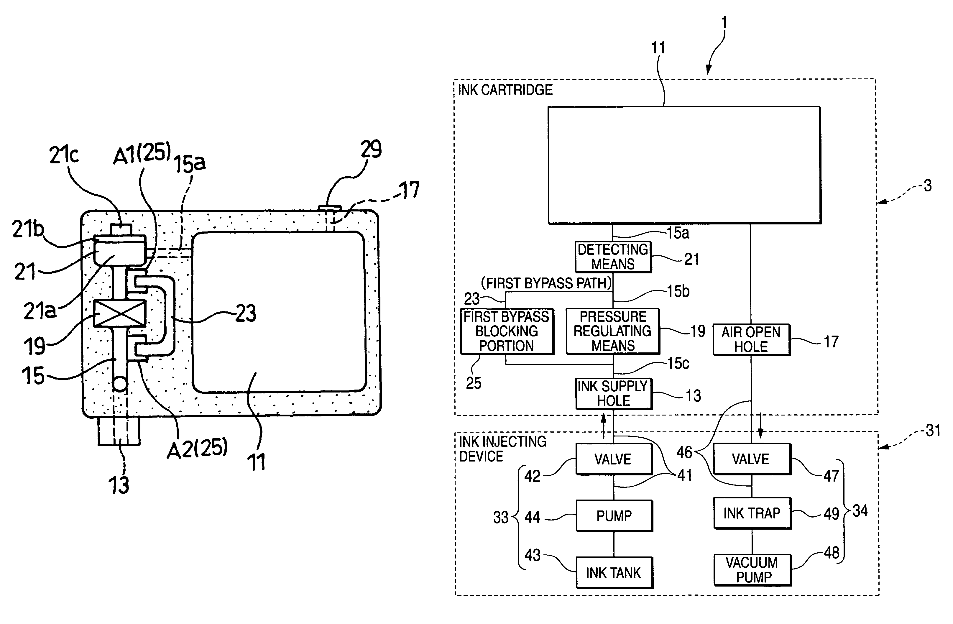
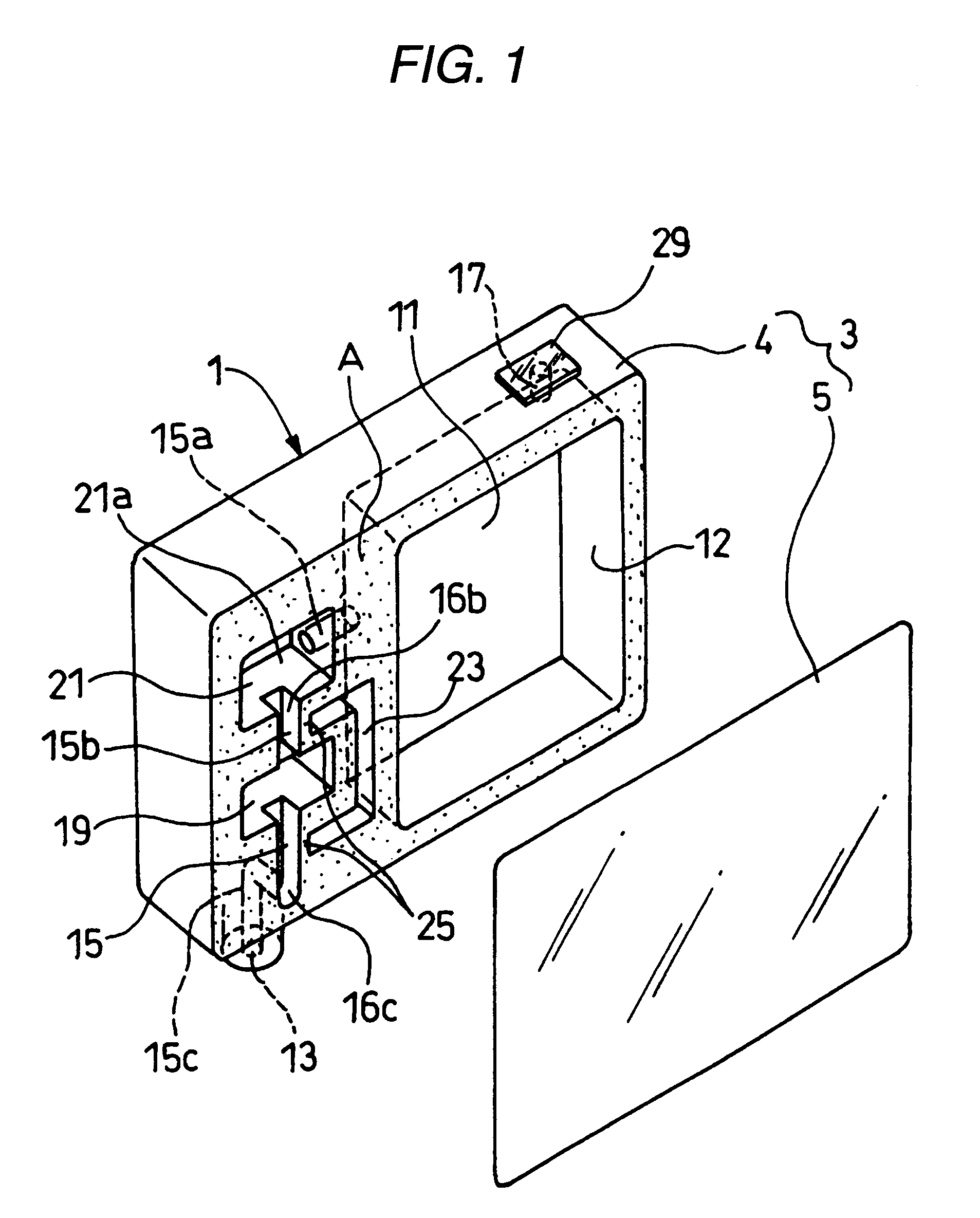
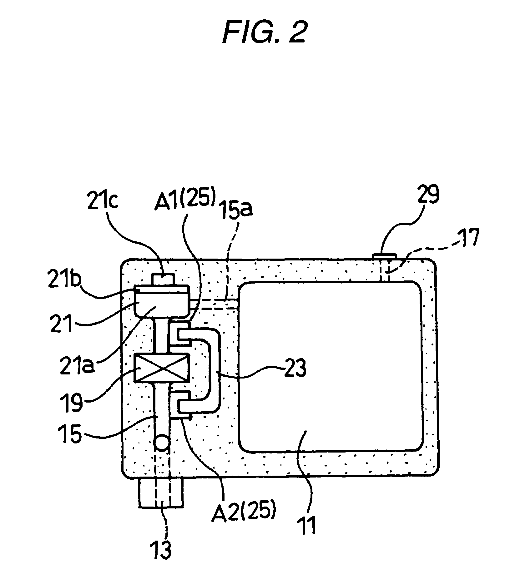
[0065]FIG. 1 is an exploded perspective view showing an ink cartridge according to the liquid container in accordance with the invention. FIG. 2 is an explanatory view showing a welding region of a seal film in a state in which a first bypass path is formed in the ink cartridge illustrated in FIG. 1. FIG. 3 is a block diagram for explaining an ink filling method of filling an ink in the ink cartridge illustrated in FIG. 1. FIG. 4 is a flowchart showing the ink filling method of filling the ink in the ink cartridge illustrated in FIG. 1. FIG. 5 is an explanatory view showing a welded portion of the seal film in a state in which the first bypass path is blocked in the ink cartridge illustrated in FIG. 1.

[0066]The arrangement and structure of each portion shown in these drawings can be changed properly.

[0067]The ink cartridge is an example of the liquid container, and is arranged to be attachable to a cartridge attachment portion of a carriage that mounts a print head (a liquid ejectin...

second embodiment

[0097]FIG. 6 is a block diagram for explaining an ink cartridge 51 and an ink filling method for the ink cartridge 51 according to the liquid container in accordance with the invention.

[0098]In the ink cartridge 51 shown in FIG. 6, a pressure reducing hole 53 is added to the structure of the ink cartridge 1 according to the first embodiment illustrated in FIG. 3.

[0099]The pressure reducing hole 53 causes the ink chamber 11 in the container body 3 to communicate with an outside, and is used for reducing a pressure in the ink chamber 11 when it is connected to the vacuum suction means 34.

[0100]The ink cartridge 51 is filled with an ink by a sequential execution of the following steps.

[0101]The air open hole 17 provided in the ink cartridge 51 is previously closed hermetically and sealed temporarily by sealing means 35.

[0102]First of all, a vacuum suction step is executed by: closing the valve 42 of the ink supply means 33 connected to the ink supply hole 13; opening the valve 47 of th...

third embodiment

[0106]FIG. 7 is a diagram for showing an ink cartridge 61 according to the liquid container in accordance with the invention, and in particular, for explaining a welding region of a seal film to form first and second bypass paths. FIG. 8 is a block diagram for explaining an ink filling method for filling an ink into the ink cartridge 61 shown in FIG. 7.

[0107]The ink cartridge 61 shown in these figures is configured such that a second bypass path 24 for connection between an upstream side of the ink detection means 21 and a downstream side thereof, a second bypass blocking portion 26 capable of blocking the second bypass path 24, an air chamber 27 and a pressure reducing hole 28 are added to the structure of the ink cartridge 1 of the first embodiment shown in FIG. 3.

[0108]The second bypass path 24 in this embodiment connects a first ink chamber 11a of the ink chamber 11 and the third ink leading passage 15c to each other, which are respectively located in the upstream side and the d...


PUM


Abstract

A liquid container includes: a container body attachable to a container attachment portion of an apparatus side; a liquid chamber, provided in the container body, for accommodating a liquid therein; a liquid supply hole connectable to a liquid receiving portion of the apparatus side; a liquid leading path for leading the liquid stored in the liquid chamber to the liquid supply hole; an air open hole for introducing outside air into the liquid chamber as the liquid in the liquid chamber is consumed; pressure regulating means, provided in a portion of the liquid leading path, for regulating a pressure of the liquid to be supplied to the liquid receiving portion through the liquid supply hole and hindering a reverse flow of the liquid from the liquid supply hole to the liquid chamber; a first bypass path for causing first and second liquid leading passages of the liquid leading path, provided respectively before and after the pressure regulating means, to communicate with each other; and a first bypass blocking portion capable of blocking the bypass path.

Description

BACKGROUND OF THE INVENTION[0001]The present invention relates to a liquid container of an air open type which is suitable as an ink cartridge to be attached to an ink jet printer, for example, and a liquid filling method of filling the liquid container with a liquid.[0002]Examples of a liquid container include an ink cartridge to be used in a printer of an ink jet type. The ink cartridge for the printer of the ink jet type has an ink chamber, provided in a container body, for accommodating an ink to be supplied to a print head. The ink cartridge can be removably fitted and attached into a cartridge attachment portion at a predetermined position in use. The ink accommodated in the ink chamber is supplied to the print head to be driven in accordance with print data transferred from a host computer and is ejected onto a target position of a print medium, such as a paper, by means of a nozzle provided on the print head.[0003]As an ink cartridge of an air open type to be attached to the...

Claims


Application Information

Patent Timeline
Patent Type & Authority Patents(United States)
IPC IPC(8): B41J2/175
CPCB41J2/17503B41J2/17506B41J2/17513B41J2/17556B41J2/175
Inventor ISHIZAWA, TAKUSHINADA, SATOSHIICHIHASHI, AKIRAYAJIMA, MINORU
Owner SEIKO EPSON CORP
Why Eureka
Try Eureka