Light tube system

a technology of light tubes and components, applied in the direction of lighting and heating apparatus, coupling device connection, instruments, etc., can solve the problems of complex configuration, high cost, and inability to firm interconnection of units, and achieve the effect of simple configuration and low cos

Inactive Publication Date: 2009-04-07
OMNILUX LIGHTING
View PDF17 Cites 28 Cited by
  • Summary
  • Abstract
  • Description
  • Claims
  • Application Information

AI Technical Summary

Benefits of technology

[0008]An advantage of the light tube holder of the present invention is its simple configuration.
[0009]Another advantage of the light tube holder of the present invention is its low cost.
[0010]Another advantage of the light tube holder of the present invention is that a light tube system can easily be made of a plurality of light tube holders.
[0012]Another advantage of the light tube holder of the present invention is that the configuration of the socket is complementary to that of the plug so as to ensure its correct connection to the other light tube holder.

Problems solved by technology

There are problems with this conventional light tube system.
Firstly, its configuration is complicated for including many complicated elements.
Secondly, its cost is high.
Thirdly, the interconnection of the units is not firm.

Method used


Image

  • Light tube system
  • Light tube system
  • Light tube system

Examples


Embodiment Construction

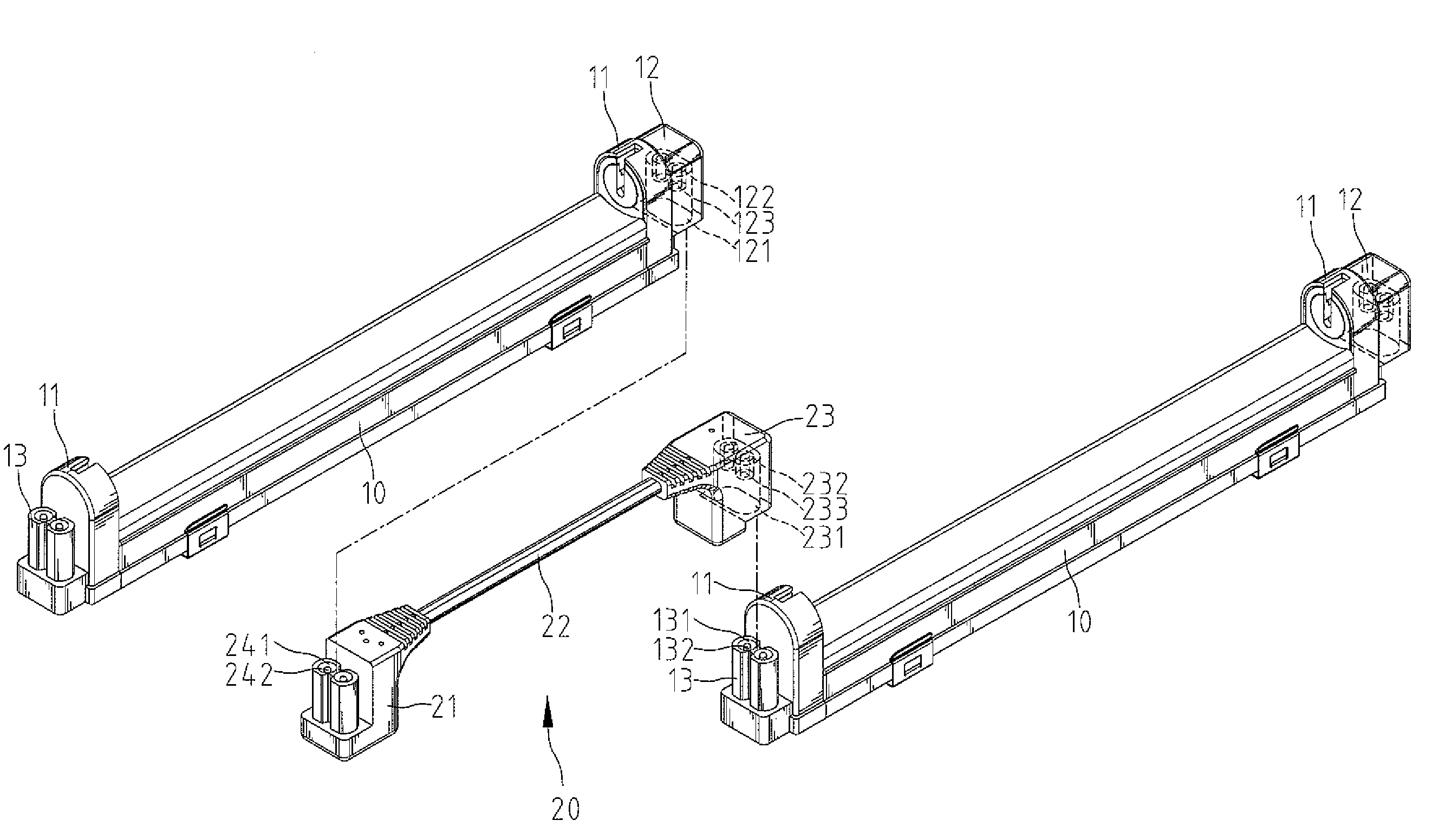
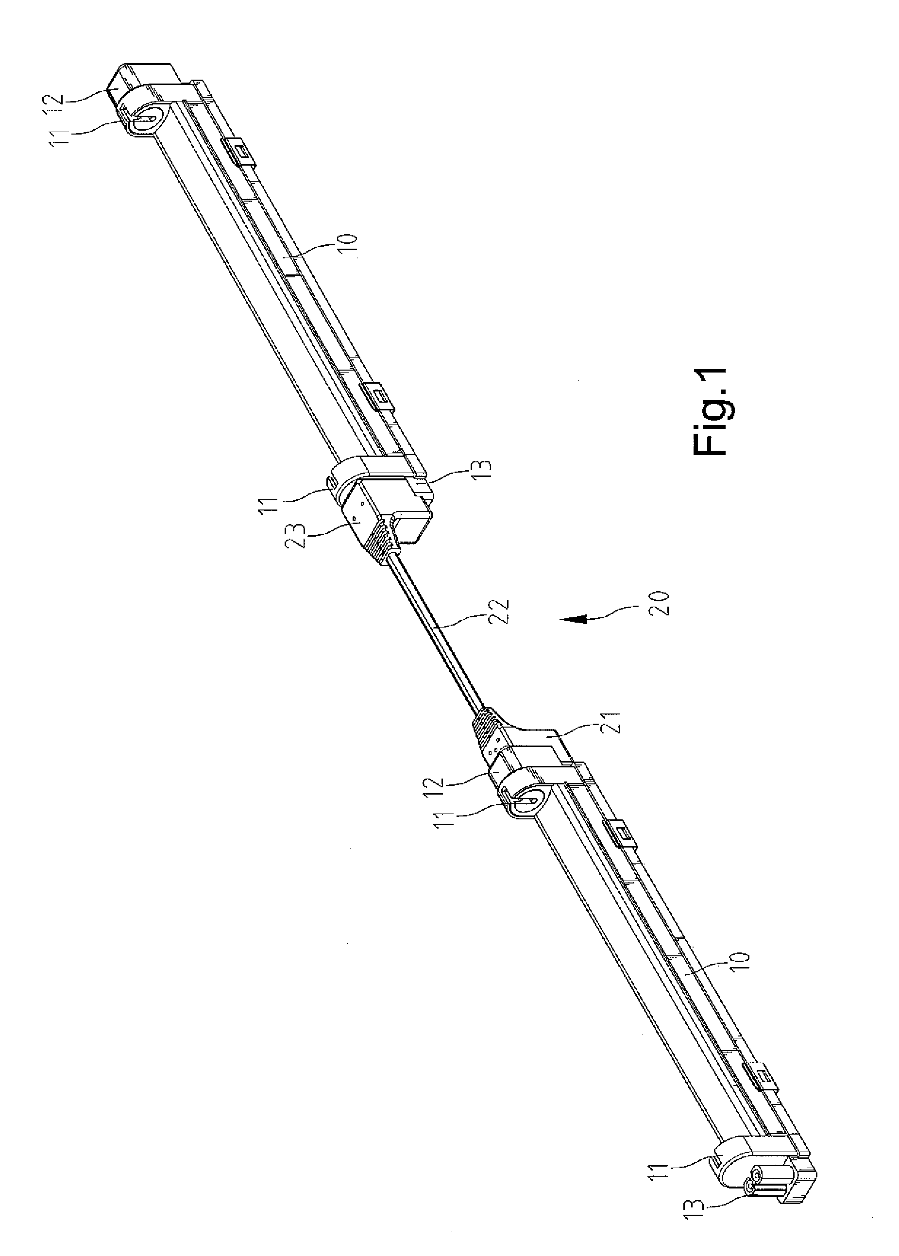
[0023]Referring to FIGS. 1 through 5, there is shown a light tube system including two light tube units and a connector 20 for interconnecting the light tube units according to the preferred embodiment of the present invention. Each of the light tube units includes a typical light tube that is omitted for the clarity of the drawings and a holder 10 for holding the light tube.

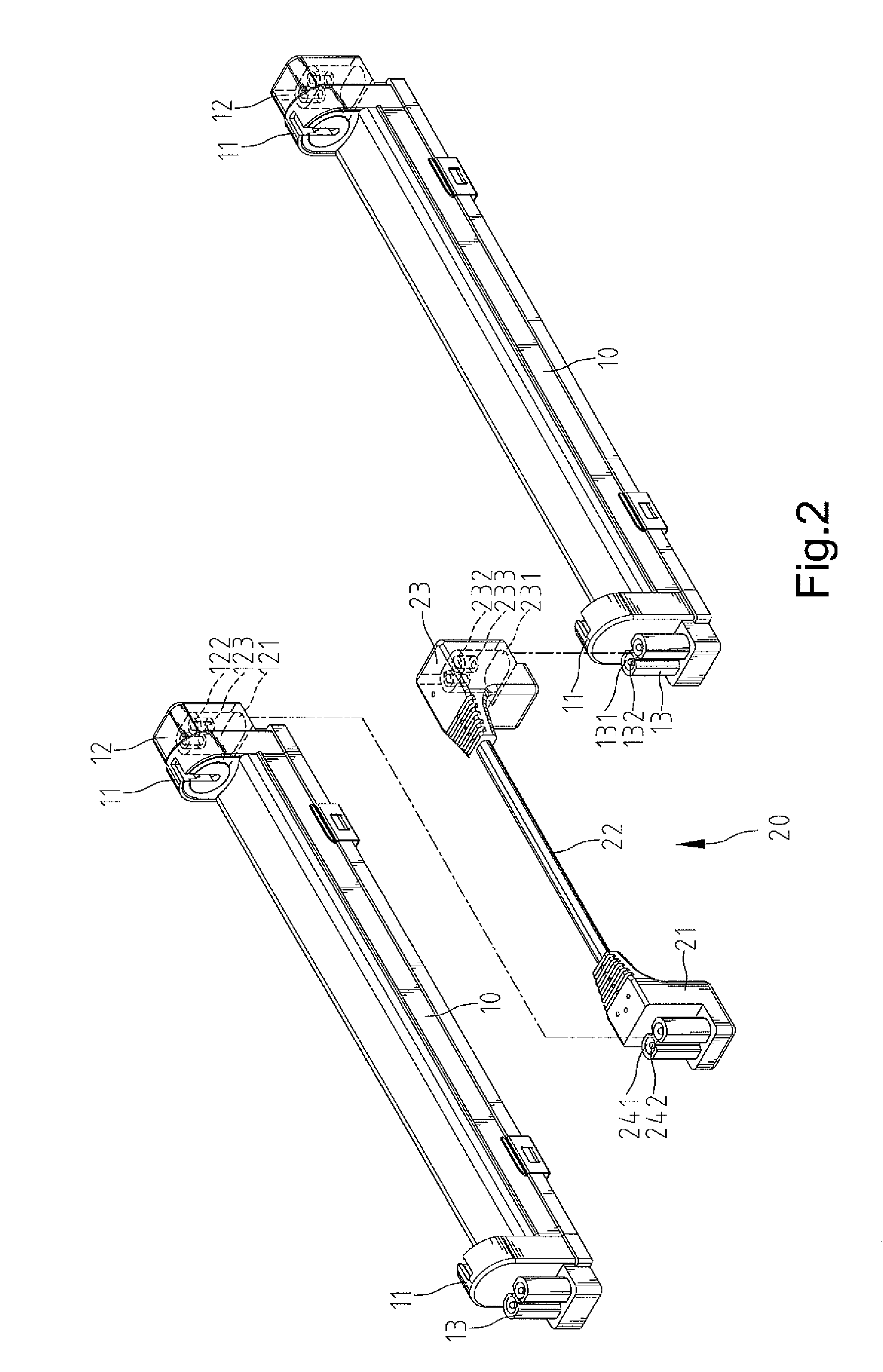
[0024]Referring to FIG. 2, each of the holders 10 includes two sockets 11 at two ends for receiving two pairs of pins of such a typical light tube, a socket 12 at one of the ends and a plug 13 at the other end.

[0025]The socket 12 includes a cap 121, two cylinders 122 protruding from the ceiling of the cap 121 and two receptacles 123 fit in the cylinders 122. The cap 121 and the cylinders 122 are electrically isolative while the receptacles 123 are electrically conductive.

[0026]The plug 13 includes two cylinders 131 and two pins 132 located in the cylinders 131. The cylinders 131 are electrically isolative while ...


PUM


Abstract

A light tube holder includes two internal sockets, an external socket and a plug. The internal sockets of the light tube holder can receive two pair of pins of a light tube. The external socket of the light tube holder can receive the plug of another light tube holder so that the light tube holders are connected to each other.

Description

BACKGROUND OF INVENTION[0001]1. Field of Invention[0002]The present invention relates to a light tube system and, more particularly, to an assembly of a holder with a connector.[0003]2. Related Prior Art[0004]Disclosed in Taiwanese Patent Publication No. 274354 is a light tube system of identical units. Each of the units includes a light tube 70, a transparent tube 10, two rings 60, two plugs 50, two caps 20 and two electric blocks 30 and 40. The rings 60 are located between the light tube 70 and the transparent tube 10. The plugs 50 are fit in the ends of the transparent tube 10. Thus, the light tube 70 is firmly located in the transparent tube 10. The electric blocks 30 and 40 are electrically connected to the light tube 70. The electric blocks 30 and 40 are located in the caps 20. The caps 20 receive the ends of the transparent tube 10. Each of the caps 20 consists of two halves. Each of the caps 20 includes a plurality of rods 22. The transparent tube 10 defines a plurality of a...

Claims


Application Information

Patent Timeline
Patent Type & Authority Patents(United States)
IPC IPC(8): F21V19/02H01R33/06H01R33/08
CPCH01R33/08H01R33/0818F21S8/031F21V23/06F21S2/005
Inventor HENDRIKUS, WESTERVELD JOHANNES
Owner OMNILUX LIGHTING
Why Eureka
Try Eureka