Workpiece conveyor and method of conveying workpiece

a workpiece and conveyor technology, applied in the direction of basic electric elements, loading/unloading, electrical equipment, etc., can solve the problems of workpiece damage, increased air consumption, and inability to convey workpieces, etc., to achieve the effect of conveying workpieces properly and efficiently, simple configuration, and small amount of air

Inactive Publication Date: 2009-04-07
SEIKO EPSON CORP
View PDF24 Cites 46 Cited by
  • Summary
  • Abstract
  • Description
  • Claims
  • Application Information

AI Technical Summary

Benefits of technology

[0012]It is an advantage of the invention to provide a workpiece conveyor which can convey a workpiece properly and efficiently by air with a simple configuration and a relatively small amount of air. It is another advantage of the invention to provide a workpiece conveyor which can convey a plurality of workpieces by air so as not to make them contact each other without applying a braking force and a repressing force. It is still another advantage of the invention to provide a workpiece conveyor and a method of conveying a workpiece which can convey a workpiece while positioning and prealigning the same at the central area of a belt without contacting the workpiece. It is yet another advantage of the invention to provide a workpiece conveyor which can convey a workpiece properly in accordance with the size thereof.
[0013]According to a first aspect of the invention, there is provided a workpiece conveyor. The workpiece conveyor comprises: a workpiece conveying path which guides the conveyance of a workpiece; and a pair of air-blowing devices which are disposed on both sides of the workpiece conveying path and blow air uniformly to the workpiece on the workpiece conveying path from both sides to give propulsion to the workpiece for conveyance.
[0014]According to this configuration, air is blown to the workpiece to give propulsion to both sides thereof uniformly. Therefore, the workpiece can be conveyed while being brought to the central area of the workpiece conveying path. As a result, the workpiece can be conveyed with its posture controlled without deviating from the workpiece conveying path.
[0015]In this case, preferably, the respective air-blowing devices include a plurality of propulsion nozzles which blow air to the side surface of the workpiece from a direction oblique to the conveying direction and are arranged side by side in the conveying direction.
[0016]According to this configuration, air can be blown to the workpiece such that a vector in the conveying direction serves as propulsion for the workpiece and a vector in a direction orthogonal to the conveying direction serves to move the workpiece to the central area of the workpiece conveying path. Furthermore, the plurality of propulsion nozzles can convey the workpiece efficiently with a small amount of air as compared with slit-like propulsion nozzles.
[0017]In this case, preferably, an interval between the plurality of propulsion nozzles of the respective air-blowing devices is shorter than one-half the length of the side surface of the workpiece.

Problems solved by technology

With the configuration of JP-A-10-157851, however, there arises a first problem that it is necessary to blow out air from both sides of the workpiece conveying path more powerfully than from the central area thereof to convey a workpiece without deviating from the workpiece conveying path.
Unfortunately, it is complicated to control air due to matters involving the blowing amount of air, the blowing direction thereof, the number and the arrangement of spouts, which cause an increased air consumption.
Incidentally, as a second problem, if the gap between the plurality of workpieces is to be maintained by physical contact, the workpieces could be damaged.
For example, when a glass substrate, etc. is used as a workpiece, there is a possibility of causing chipping or invisible cracking at contact points.
It is of particular note that, this kind of cracks tend to be overlooked at the inspection stage, and the trouble is that cracks are liable to be found after workpieces have been manufactured.
With the configuration of JP-A-2003-063636, furthermore, there arises a third problem that a workpiece is damaged due to physical contact because the plurality of groups of poles are made contact with the conveyed workpiece to make the same positioned at the central area of the roller conveyor.
For example, when a glass substrate, etc. is used as a workpiece, there is a possibility of causing chipping or invisible cracking at contact points.
It is of particular note that, this kind of cracks tend to be overlooked at the inspection stage, and the trouble is that cracks are liable to be found after workpieces have been manufactured.
With the configuration of JP-A-10-087042, furthermore, there arises a fourth problem, in addition to those described above, that a workpiece smaller in size than that mountable on the pair of belt conveyors cannot be conveyed because the pair of belt conveyors are fixedly provided.
It is not possible, therefore, to perform conveyance according the size of a workpiece.

Method used


Image

  • Workpiece conveyor and method of conveying workpiece
  • Workpiece conveyor and method of conveying workpiece
  • Workpiece conveyor and method of conveying workpiece

Examples


second embodiment

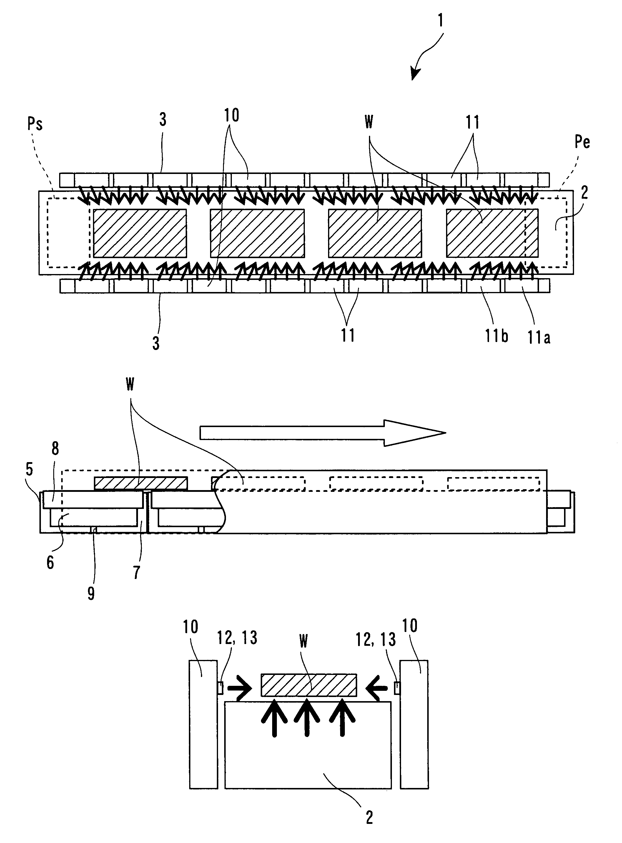
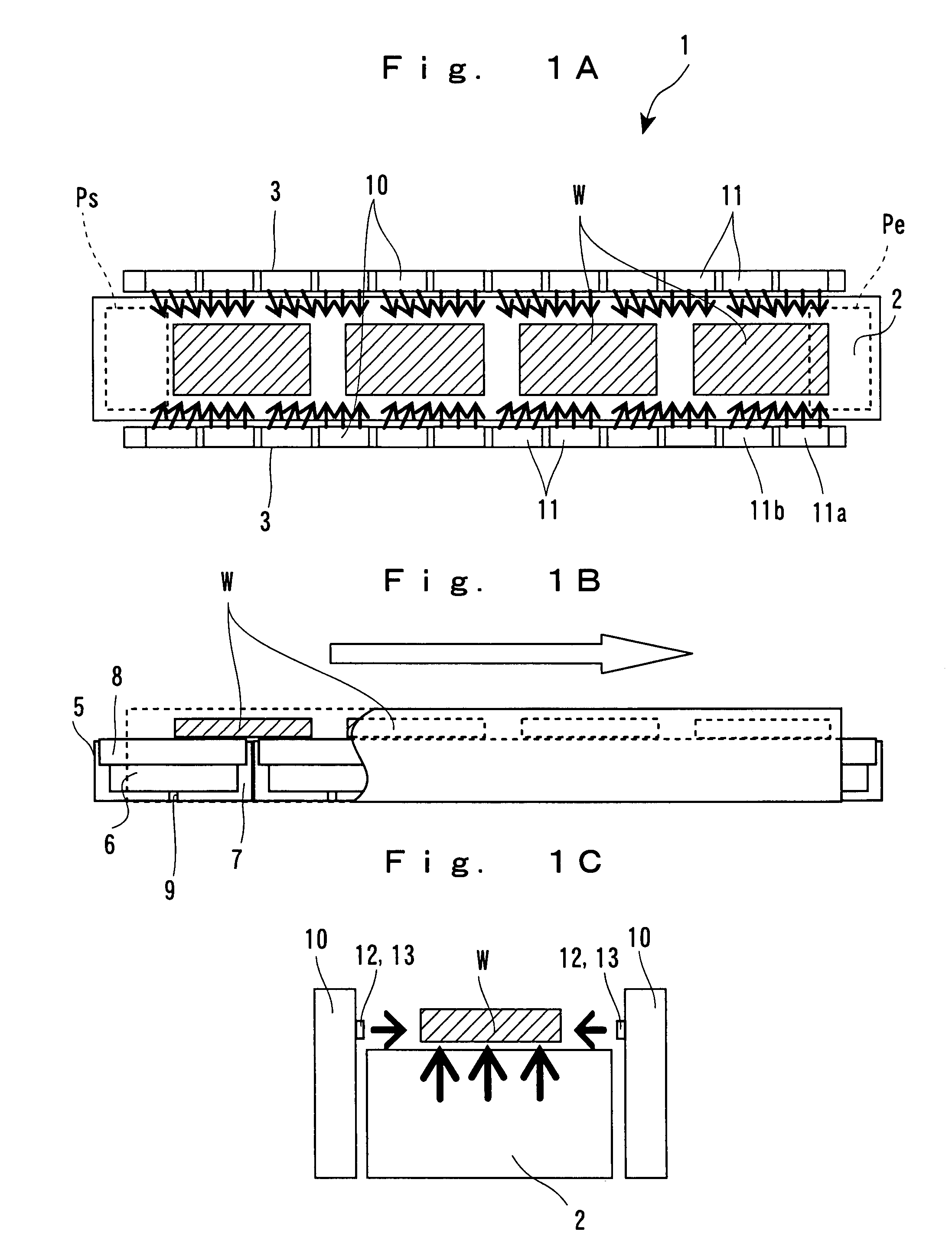
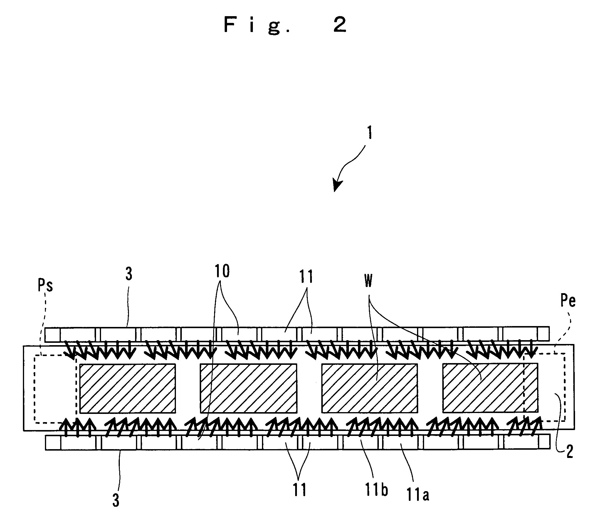
[0116]Referring next to FIGS. 6A to 6C, a description will be made about the workpiece conveyor of a Note that only different parts will be described herein to avoid overlaps. The workpiece conveyor 1 includes: a workpiece conveying mechanism 4 composed of the above-described workpiece conveying path 2 serving as a conveying path for a plurality of workpieces W and composed of the above-described pair of air-blowing units 3 which are standingly provided along both sides of the workpiece conveying path 2 and give propulsion to the workpiece W; a plurality of intermediate air-dropping units 55 which are disposed above the workpiece conveying path 2 and maintain gaps between the plurality of conveyed workpieces W; a baffle plate 66 which is disposed ahead of the conveyance ending position Pe of the workpiece conveying path 2 and extends in a direction orthogonal to the conveying direction; and an end air-dropping unit 77 which blows air from above to the gap between the baffle plate 6...

third embodiment

[0123]Referring next to FIGS. 8A to 8C, a description will be made about the workpiece conveyor according to a The workpiece conveyor used herein has a workpiece such as a glass substrate used with a liquid crystal panel mounted on a belt conveyor and conveys the same. At that time, the workpiece conveyor makes it possible to perform prealignment of the workpiece. The workpiece conveyor 1 includes a belt conveyor 20 and the pair of air-blowing units 3 standingly provided along both sides of the belt conveyor 20. The pair of air-blowing units 3 extend slightly shorter in length than the belt conveyor 20 from the conveyance starting position Ps to the conveyance ending position Pe of the belt conveyor 20 and blow air to the workpiece W conveyed by the belt conveyor 20 from both sides.

[0124]The belt conveyor 20 includes: a driving pulley 50 which is rotated by a driving motor (not shown) through a reduction gear train or the like; a driven pulley 60 which is driven by the driving pull...

fourth embodiment

[0129]Referring next to FIGS. 10A to 10C, a description will be made about the workpiece conveyor according to a The workpiece conveyor 1 includes: the pair of belt conveyors 20 on which the workpiece w is straddlingly mounted and conveyed; separation distance adjusting mechanisms 90 which are provided at the front and rear parts of the pair of belt conveyors 20 in the conveying direction and adjust a separation distance between the pair of belt conveyors 20; and the pair of air-blowing units 3 provided along both sides of the pair of belt conveyors 20. The pair of air-blowing units 3 extend slightly shorter in length than the pair of belt conveyors 20 from the conveyance starting position Ps to the conveyance ending position Pe of the pair of belt conveyors 20 and blow air to the workpiece W conveyed by the pair of belt conveyors 20.

[0130]The respective belt conveyors 20 include: the driving pulley 50 which is rotated by a driving motor (not shown) through a reduction gear train o...


PUM


Abstract

There is provided a workpiece conveyor including a workpiece conveying path which guides the conveyance of a workpiece; and a pair of air-blowing devices which are disposed on both sides of the workpiece conveying path and blow air uniformly to the workpiece on the workpiece conveying path from both sides to give propulsion to the workpiece for conveyance.

Description

[0001]The entire disclosure of Japanese Patent Application Nos. 2006-064355, 2006-064356, 2006-064354, and 2006-064359 filed Mar. 9, 2006 is expressly incorporated by reference herein.BACKGROUND[0002]1. Technical Field[0003]The present invention relates to a workpiece conveyor which conveys a workpiece by a belt conveyor, air, or the like and a method of conveying a workpiece.[0004]2. Related Art[0005]A known workpiece conveyor is of a type which blows out air upwardly from a workpiece conveying path, on which a workpiece is conveyed, to float the workpiece while blowing out air from both sides of the workpiece conveying path more powerfully than from the central area thereof to guide the workpiece to the central area. In this state, the workpiece conveyor blows out air from spouts provided in the workpiece conveying path in the conveying direction to give propulsion to the workpiece for conveyance. Reference is made to JP-A-10-157851 as an example of related art. According to this ...

Claims


Application Information

Patent Timeline
Patent Type & Authority Patents(United States)
IPC IPC(8): B65G51/00
CPCB65G47/22B65G49/065B65G51/02B65G51/03H01L21/67784B65G2249/04B65G2249/045H01L21/68
Inventor HAYASHI, TAKAYUKIYAMASHITA, SEIICHIRO
Owner SEIKO EPSON CORP
Why Eureka
Try Eureka