Method for regulating the vacuum supply of calibration tools

a technology of calibration tools and vacuum supply, which is applied in the field of regulating the vacuum supply of calibration tools, can solve the problems of high energy cost, high production cost, and inability to reduce, so as to increase the quality of the profile produced and increase the accuracy

Inactive Publication Date: 2009-04-07
TECHNOPLAST KUNST GES
View PDF26 Cites 0 Cited by
  • Summary
  • Abstract
  • Description
  • Claims
  • Application Information

AI Technical Summary

Benefits of technology

[0010]Another advantage of the method of the invention is that the negative pressure in the calibration tools is regulatable with less variation so that the quality of the profiles produced can be increased.
[0014]In terms of energy, it is preferred that on the air side the dry calibration tool communicates with the common pressure tank only and that on the air side the calibration bath communicates with the common pressure tank only. This permits to largely prevent energy losses through the control valves. A particularly advantageous operating behaviour can be achieved in that the common pressure tank preferably comprises at least one volume that corresponds to the nominal pump capacity of all of the vacuum pumps of one to five seconds at the pressure target value of the common pressure tank. This more specifically permits to keep the pressure variations within narrow limits by alternately switching discrete vacuum pumps on and off. In this context, a number of between three and five pumps introduces a greater effect of benefit. A sufficiently fine gradation in the total output energy of the vacuum pumps is thus ensured at a reasonable expense in terms of apparatus.

Problems solved by technology

The disadvantage thereof is that, in most of the operating conditions of the vacuum pumps, the vacuum produced is too high and has to be reduced in order to prevent damage to the profile.
Although the method described permits to keep the pressure within a tool on a predetermined level, the energy expense is quite high.

Method used


Image

  • Method for regulating the vacuum supply of calibration tools
  • Method for regulating the vacuum supply of calibration tools

Examples


Embodiment Construction

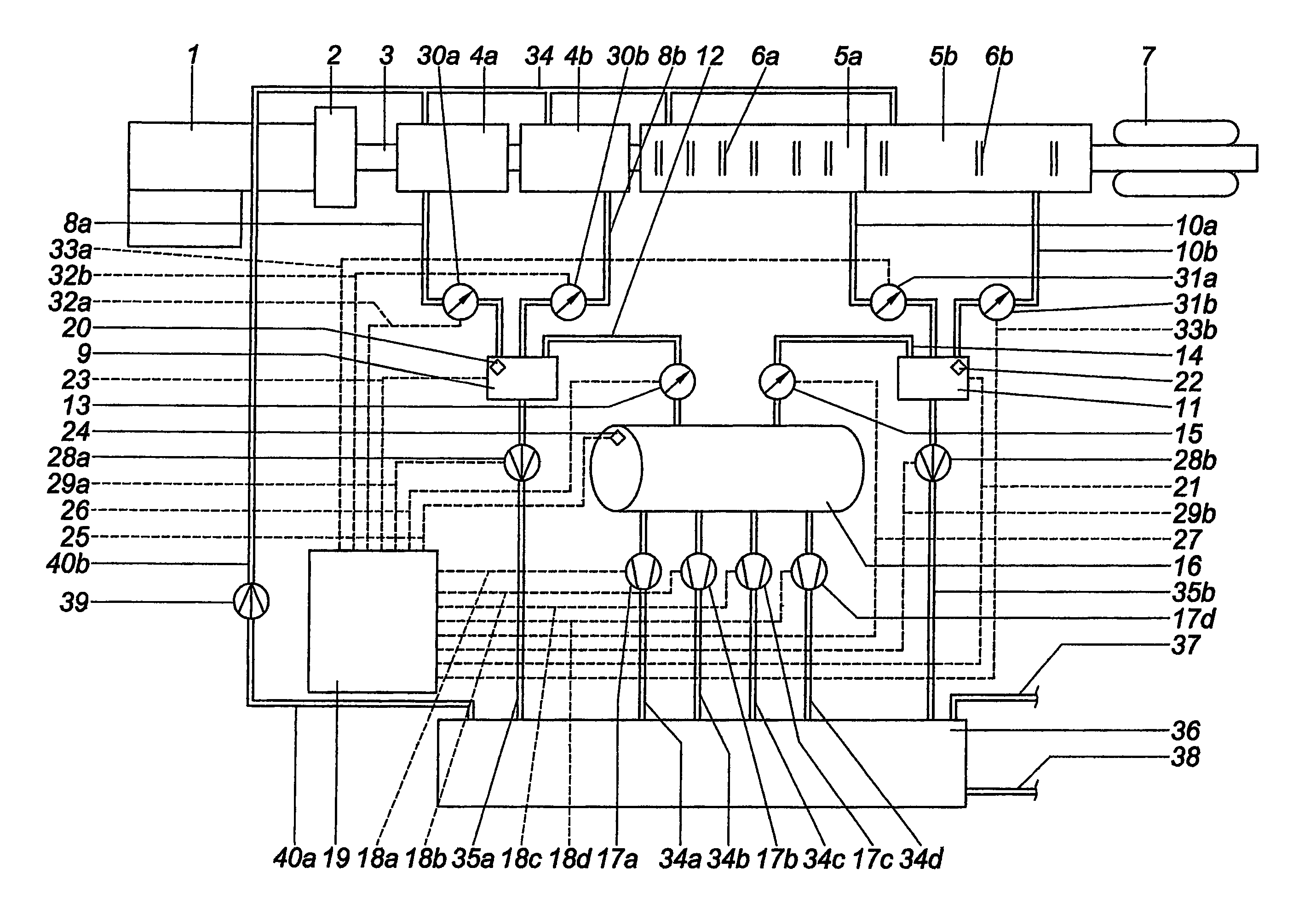
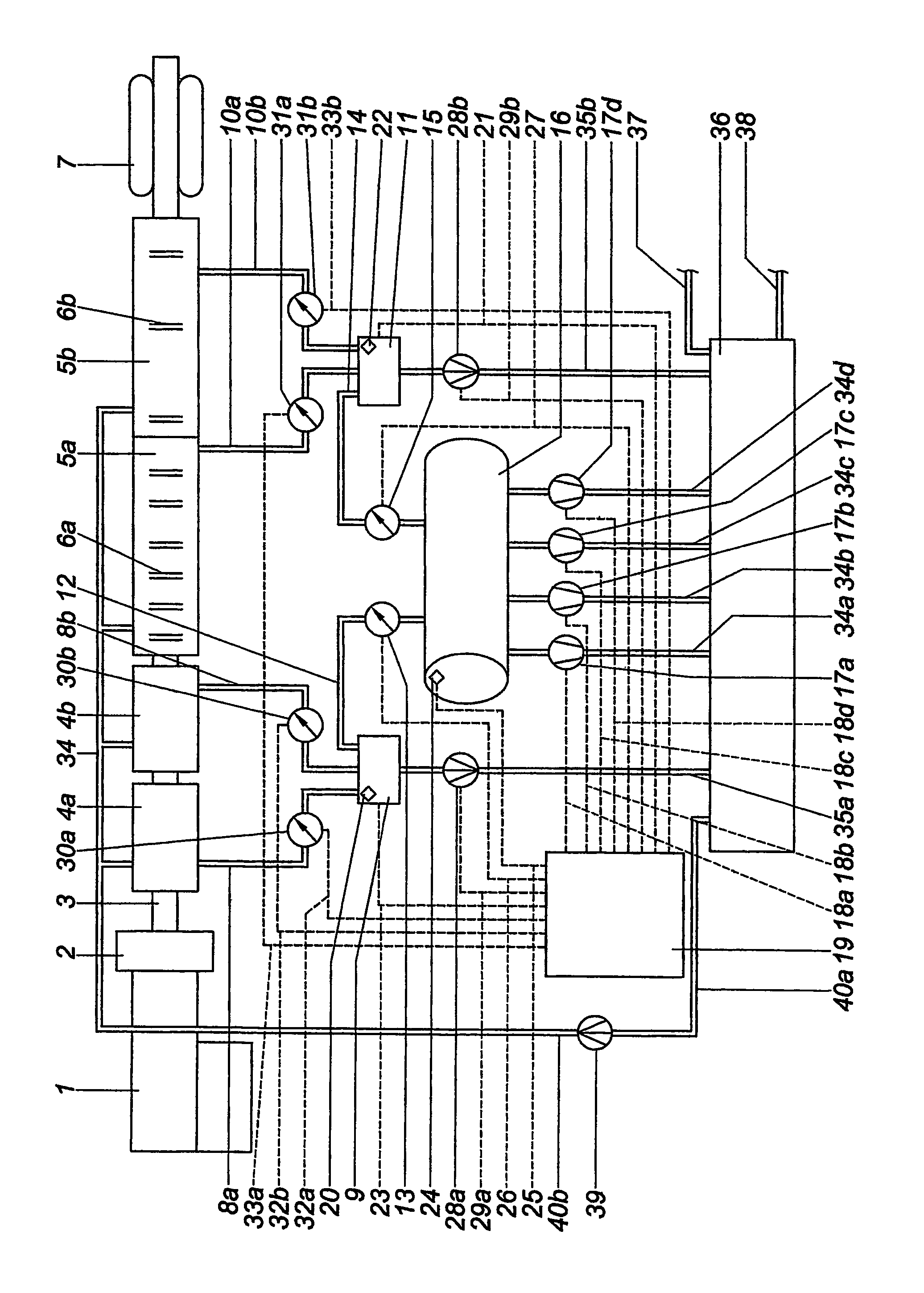
[0017]In the FIGURE, the extrusion line consists of an extruder 1 with an extrusion die 2 for producing a plastic profile 3. The plastic profile 3 is cooled and calibrated in a first dry calibration tool 4a. Downstream of the first dry calibration tool 4a there is disposed another dry calibration tool 4b that is adjoined downstream thereof with a calibration bath 5a having a plurality of screens 6 that may in turn be adjoined with further calibration baths like for example in the present exemplary embodiment the additional calibration bath 5b. A caterpillar draw-off unit 7, which is schematically illustrated herein, serves to apply to the profile 3 the tensile force required.

[0018]The dry calibration tools 4a, 4b communicate with a first water separator 9 through vacuum lines 8a, 8b. In the same manner, the calibration baths 5a, 5b are connected to a second water separator 11 through vacuum lines 10a, 10b.

[0019]The water separators 9, 11 serve to separate a coolant that has possibl...


PUM

PropertyMeasurementUnit
pressureaaaaaaaaaa
pressureaaaaaaaaaa
pressureaaaaaaaaaa

Abstract

A method and apparatus for regulating the vacuum supply to calibration tools which include at least one dry calibration tool and at least one calibration bath, wherein at least one vacuum pump is brought into contact with a calibration tool in order to extract air from the calibration tool, the pressure in the tool being regulated to a target value by means of a control valve. Several vacuum pumps extract air from a common pressurized container, and the air is extracted from at least one dry calibration tool by a first control valve in the common pressurized container and in addition the air is extracted from at least one calibration bath by a second control valve in the common pressurized container.

Description

BACKGROUND OF THE INVENTION[0001]1. Field of the Invention[0002]The invention relates to a method for regulating the vacuum supply of calibration tools, the tools including at least one dry calibration tool and at least one calibration bath, by which at least one vacuum pump is brought into contact with a calibration tool in order to draw air from the calibration tool, the pressure in the calibration tool being regulated to a target value by means of a control valve.[0003]2. The Prior Art[0004]An extrusion line for producing plastic profiles usually consists of an extruder with an extrusion die that is adjoined with calibration tools for calibrating and cooling the produced profile. Directly downstream of the extrusion die, what are termed dry calibration tools are mostly utilized, these generally being water-cooled metal blocs having a calibration port that conforms to the outer contour of the profile and that is laterally adjoined with vacuum slots. The vacuum slots communicate wi...

Claims


Application Information

Patent Timeline
Patent Type & Authority Patents(United States)
IPC IPC(8): F04B41/06B28B5/00B29C48/96B29C48/90B29C48/92
CPCB29C47/90B29C47/903B29C47/904B29C47/905B29C47/92B29C47/003B29C2791/006B29C2947/92019B29C2947/92466B29C2947/92514B29C2947/92923B29C2947/92961B29C48/905B29C48/12B29C48/90B29C48/903B29C48/904B29C48/92B29C2948/92019B29C2948/92466B29C2948/92514B29C2948/92923B29C2948/92961
Inventor SCHWAIGER, MEINHARD
Owner TECHNOPLAST KUNST GES
Why Eureka
Try Eureka