Power supply system

a power supply system and power supply technology, applied in the direction of fixed transformers, cores/yokes, transportation and packaging, etc., can solve the problems of increasing size and cost, and achieve the effect of simplifying the configuration of load devices

Inactive Publication Date: 2009-04-07
MATSUSHITA ELECTRIC WORKS LTD
View PDF2 Cites 250 Cited by
  • Summary
  • Abstract
  • Description
  • Claims
  • Application Information

AI Technical Summary

Benefits of technology

[0011]In view of the foregoing and other problems, it is an object of the present invention to provide a power supply system that can feed electric power from a single power adaptor to a plurality of load devices in a contactless manner, while simplifying the configuration of the load devices.

Problems solved by technology

This leads to an increase in size and costs.

Method used


Image

  • Power supply system
  • Power supply system
  • Power supply system

Examples


first embodiment

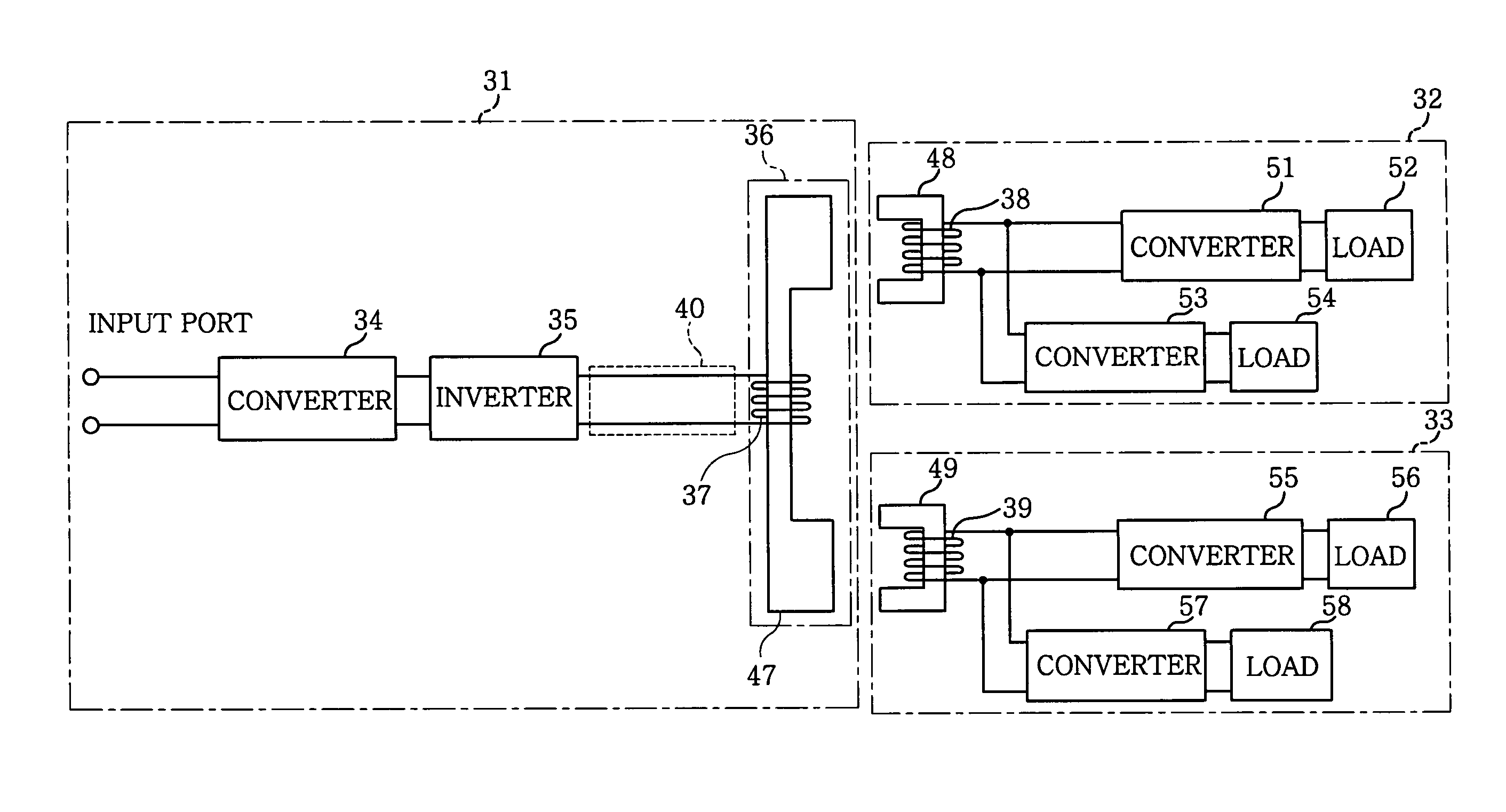
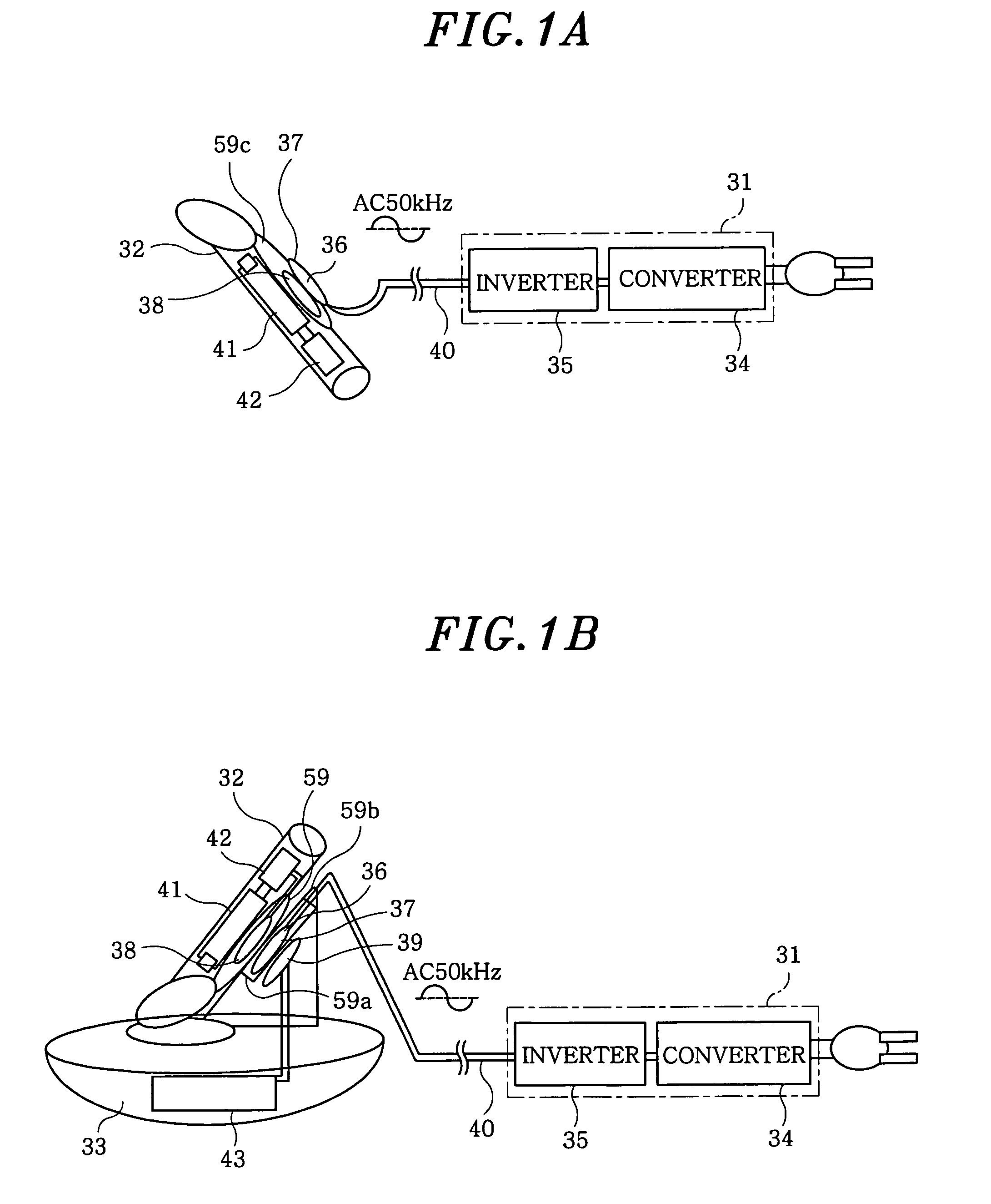
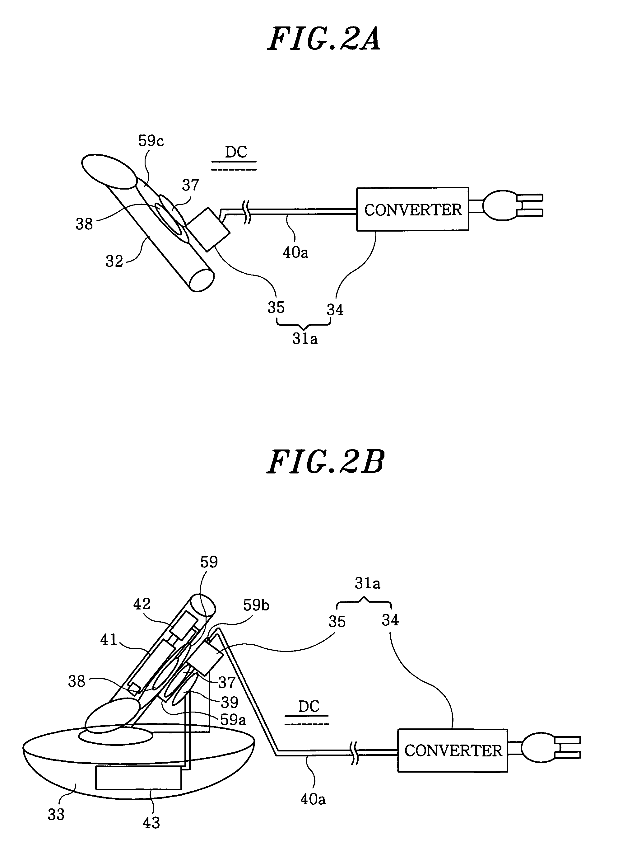
[0049]FIGS. 1A to 2B show configurations of a power supply system in accordance with a first embodiment of the present invention. The power supply system is for use in an electric shaver with a cleaning device. As shown in FIGS. 1A and 2A, an electric shaver 32 can be connected to a single power adapter 31 or 31a. As illustrated in FIGS. 1B and 2B, a cleaning device 33 can also be connected to the power adapter 31 or 31a. Referring to FIGS. 1B and 2B, it is possible not only to cleanse a knife edge of the electric shaver 32 but also to electrically charge the electric shaver 32 under the state that the electric shaver 32 is mounted on the cleaning device 33.

[0050]The power adapter 31 or 31a includes a converter 34, which is formed of a diode bridge, a smoothing capacitor and the like, and a voltage-resonant inverter 35. The power adapter 31 or 31a is adapted to output an alternating current of, e.g., 50 kHz and 30V, to a power transmission coil 37 of a single power feeding plug 36 t...

second embodiment

[0067]FIGS. 10A and 10B show configurations of a power supply system in accordance with a second embodiment of the present invention. The power supply system is for use in an electric shaver with a cleaning device and is similar to the system shown in FIGS. 1A to 2B. Corresponding parts will be designated by like reference numerals, with no description given in that regard. Attention is invited to the fact that, in the system of this embodiment, a power feeding plug 76 of a power adapter 71 is formed into a wedge shape, as illustrated in FIG. 10B, in order to cope with the inclined mounting of the electric shaver 32 on the cleaning device 73. As in the power adapter 31a illustrated in FIGS. 2A and 2B, the converter 34 and the voltage-resonant inverter 35 may be separated from each other, with a direct current being transmitted through the power cable 40a.

[0068]An induction heating coil 74 for drying a blade of the electric shaver 32 by induction heating is connected to the cleaning...

third embodiment

[0074]FIGS. 13 through 15 are perspective views showing the structures of cores 97a-99a, 97b-99b and 97c-99c wound with a power transmission coil 37 and power receiving coils 38 and 39 in a power supply system in accordance with a third embodiment of the present invention. In respect of the respective cores 97a-99a, 97b-99b and 97c-99c, it is to be noted that the cores 98a, 98b, 98c, 99a, 99b and 99c wound with the power receiving coils 38 and 39 are arranged on one side of the cores 97a, 97b and 97c wound with the power receiving coil 37.

[0075]In the cores 97a, 98a and 99a shown in FIG. 13, the secondary cores 98a and 99a are of an “E”-like shape as with the secondary cores 48b and 49b illustrated in FIG. 5. The primary core 97a is of a structure in which two “E”-like cores are connected to each other in a longitudinal direction in such a fashion that the primary core 97a can face the secondary cores 98a and 99a arranged on one side thereof in a longitudinal (vertical) direction. F...


PUM

PropertyMeasurementUnit
voltageaaaaaaaaaa
frequencyaaaaaaaaaa
electric poweraaaaaaaaaa

Abstract

A power supply system is capable of feeding electric power from a power adapter to a plurality of load devices. The power adapter includes a primary core; and a primary coil wound around the primary core for serving as a output port of the power adapter to output an alternating current. The load devices include secondary cores for simultaneously forming magnetic circuits between the primary core and the load devices; and secondary coils wound around the secondary cores for feeding output power to the load devices. The primary core has two pairs of protrusions, and the secondary cores are arranged on opposite sides of the primary core in such a manner that the primary core lies between the secondary cores to feed electric power simultaneously to the load devices.

Description

FIELD OF THE INVENTION[0001]The present invention relates to a power supply system capable of feeding electric power from a single power adaptor to a plurality of load devices and, more specifically, to a power supply system in which a power feeding operation is performed by contactless power transmission based on electromagnetic induction.BACKGROUND OF THE INVENTION[0002]One example of power supply systems capable of feeding electric power from a single power adaptor to a plurality of load devices is an electric shaver with a cleaning device. FIGS. 21A and 21B show configurations of a power supply system for use in the electric shaver. As shown in FIG. 21A, an electric shaver 2 can be connected to a power adapter 1 which is formed of a RCC (ringing choke converter) and the like. As illustrated in FIG. 21B, a cleaning device 3 can also be connected to the power adapter 1. As depicted in FIG. 21B, it is possible not only to cleanse a blade of the electric shaver 2 but also to electri...

Claims


Application Information

Patent Timeline
Patent Type & Authority Patents(United States)
IPC IPC(8): H01F27/42H02J7/00B26B19/38H01F38/14
CPCH01F38/14H02J5/005H01F3/00H01F30/04H02J50/402H02J50/70H02J50/12H02J50/005H02J50/10H02J7/02
Inventor ABE, HIDEAKIKITAMURA, HIROYASUYAMASHITA, MIKIHIRO
Owner MATSUSHITA ELECTRIC WORKS LTD
Why Eureka
Try Eureka