Stereoscopic image display unit

a stereoscopic image and display unit technology, applied in the field of stereoscopic image display units, can solve the problems of observing the quality of display, and the failure of portions that should be displayed in black to be displayed sufficiently black, and achieve the effects of deterioration in display quality, low deformation, and high strength

Inactive Publication Date: 2009-04-07
138 EAST LCD ADVANCEMENTS LTD
View PDF9 Cites 14 Cited by
  • Summary
  • Abstract
  • Description
  • Claims
  • Application Information

AI Technical Summary

Benefits of technology

[0040]Thanks to the employment of the foregoing structures, the stereoscopic image display unit of the present invention yields the excellent effects now described below. Namely:
[0041]According to the stereoscopic image display unit of claim 1 of the present invention, a shielding member for blocking light that has entered through an edge surface of said transparent plate is provided in the vicinity of the boundary of the parallax barrier's effective display area, so that even in the case where the transparent plate is thick and stray light entering through the edge surface of the transparent plate would, with the conventional structure, exit through the parallax barrier, such light will be blocked out by said shielding member and thus will not emerge from the parallax barrier. As a result, deterioration in the display quality such as blurring of the image in the vicinity of the boundary of the effective display area of the stereoscopic image display unit, or failure of the portions that should be displayed in black to be displayed sufficiently black, will not occur.
[0042]According to the stereoscopic image display unit of claim 2 of the present invention, a glass plate or an acrylic resin plate may be used for said transparent plate; if a glass plate is used, then due to its high strength there will little deformation even when the stereoscopic image display unit is large-sized, and hence it will be possible to obtain a stereoscopic image display unit with good display quality.
[0043]According to the stereoscopic image display unit of claim 3 of the present invention, the thickness of the transparent plate is 5 cm or greater, so that the beneficial effects of applying the present invention are manifested to a pronounced degree. This is because, owing to the relation between the transparent plate's refractive index and thickness, it is when the thickness of the transparent plate is 5 cm or greater that deterioration in the display quality such as blurring of the image in the vicinity of the boundary of the effective display area of the stereoscopic image display unit or failure of the portions that should be displayed in black to be displayed sufficiently black, becomes markedly noticeable. The upper limit on the transparent plate's thickness is determined according to the distance between the viewer and the stereoscopic image display unit, and hence is not of critical significance. But the longer that distance is, the thicker it will be necessary to make the transparent plate, and an over-thick transparent plate will weigh so much as to be impractical. Accordingly, such upper limit should preferably be set at around 10 cm.
[0044]According to the stereoscopic image display unit of claim 4 of the present invention, it is easily possible, by using commonly-known photolithographic processes, to form as the shielding member a black mask, which is a well-known shielding means.
[0045]According to the stereoscopic image display unit of claim 5 of the present invention, the liquid crystal parallax barrier can in a simple manner be made to form black-and-white stripes of any desired width and spacing, or rendered transparent over its entire surface, so that the unit can switch with ease between a 2D display and a 3D display.

Problems solved by technology

But when the thickness of the transparent plate 20 is increased, or more specifically, when the transparent plate 20 is made thicker than approximately 5 cm, problems in display quality are observed to occur such as blurring of the image in the vicinity of the boundary of the effective display area of the stereoscopic image display unit, or failure of the portions that should be displayed in black to be displayed sufficiently black.

Method used


Image

  • Stereoscopic image display unit
  • Stereoscopic image display unit
  • Stereoscopic image display unit

Examples


embodiment 1

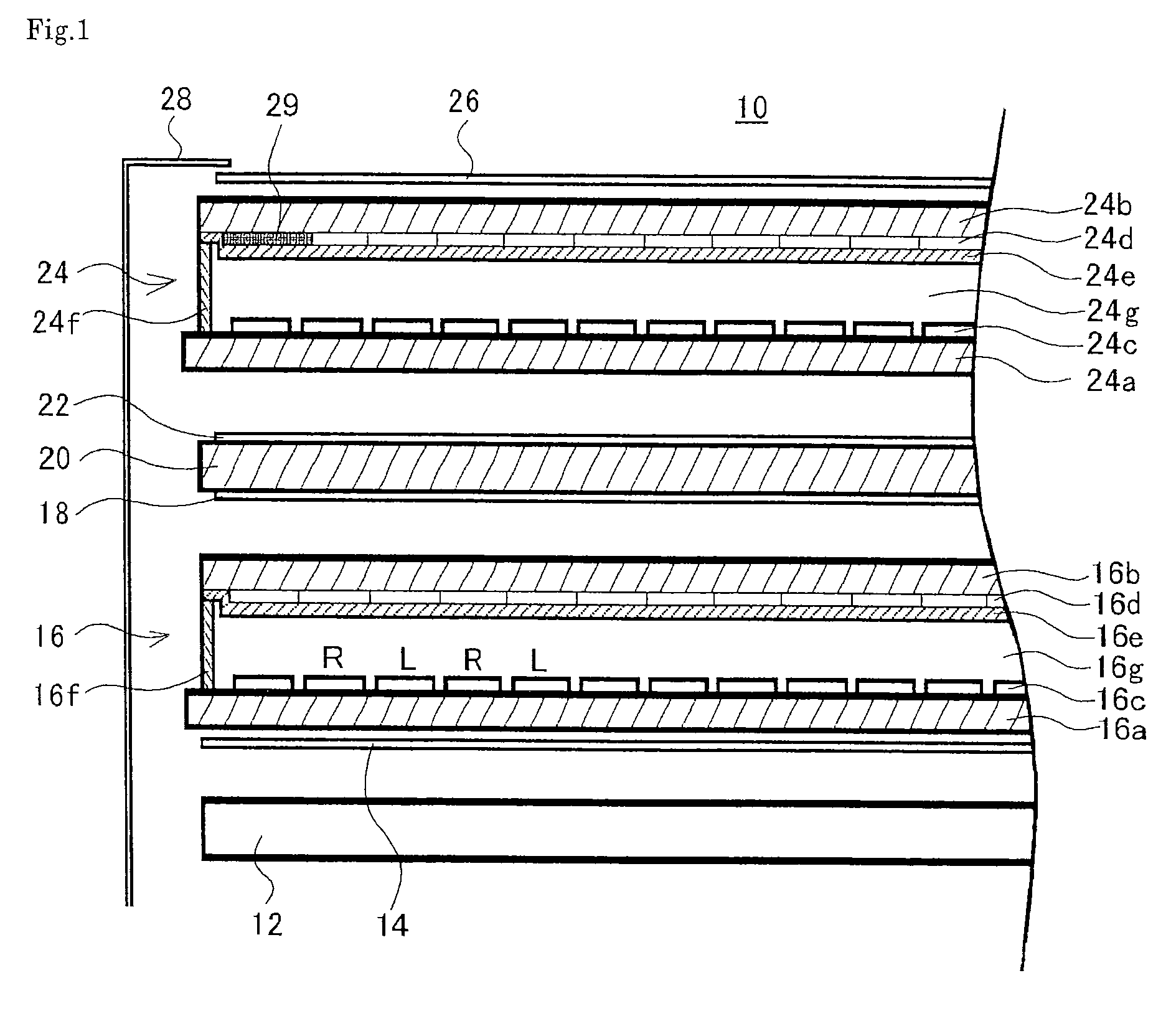
[0069]FIG. 1 is a partial exploded cross-sectional view of a parallax barrier type stereoscopic image display unit 10 of Embodiment 1. Those components in FIG. 1 that are the same as or similar to those of the prior art parallax barrier type stereoscopic image display unit in said FIG. 4 are given the same or similar reference numerals, and detailed descriptions of such same or similar components are omitted. In this parallax barrier type stereoscopic image display unit 10:

a transmitting liquid crystal display panel 16 having an array of display pixels is deployed over the outer face of a backlight 12 with a first polarizing plate 14 interposed;

then a liquid crystal parallax barrier 24 is deployed with a second polarizing plate 18, a transparent plate 20 of, for example, glass, and a third polarizing plate 22 interposed;

and over the outer face of the liquid crystal parallax barrier 24 is deployed a fourth polarizing plate 26.

[0070]In the liquid crystal parallax barrier 24, liquid cr...

embodiment 2

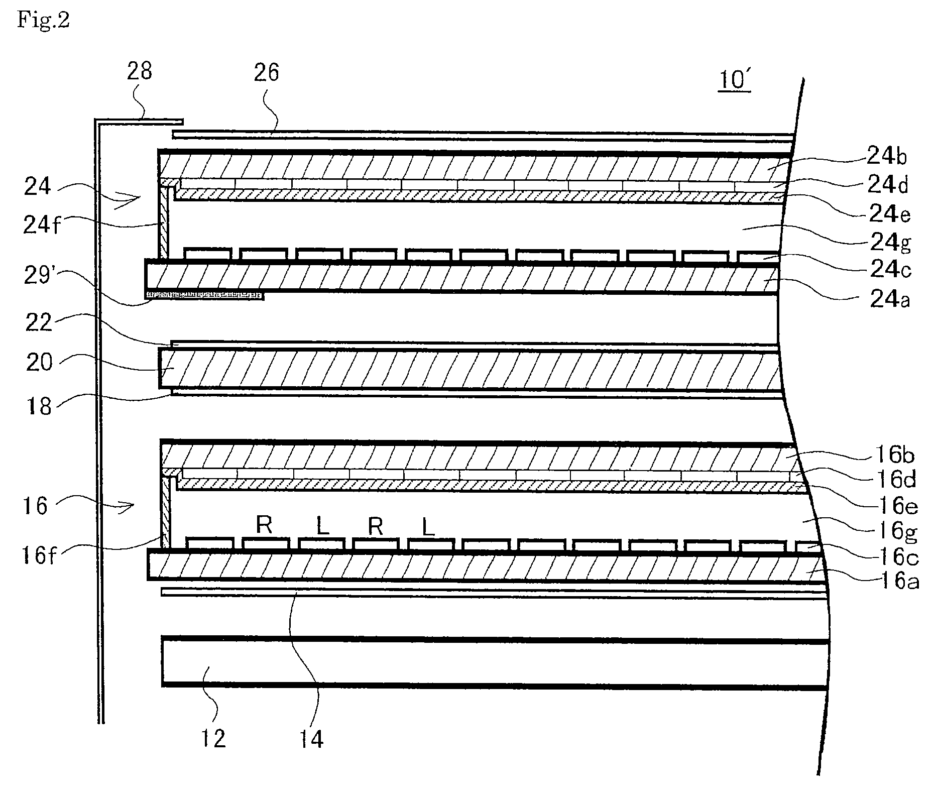
[0075]FIG. 2 is a partial exploded cross-sectional view of a parallax barrier type stereoscopic image display unit 10′ of Embodiment 2. Those components in FIG. 2 that are the same as or similar to those of the Embodiment 1 parallax barrier type stereoscopic image display unit 10 in said FIG. 1 are given the same or similar reference numerals, and detailed descriptions of such same or similar components are omitted.

[0076]The parallax barrier type stereoscopic image display unit 10′ of Embodiment 2 differs structurally from the stereoscopic image display unit 10 of Embodiment 1 in that the black mask or other shielding member 29′ is provided not in the interior of the liquid crystal parallax barrier 24 but on the outer face of the liquid crystal parallax barrier 24's glass substrate 24a, which faces the transparent plate 20.

[0077]When such structure is employed, not only will it be easy to provide the black mask or other shielding member 29′ on the outer face of the glass substrate 2...


PUM

PropertyMeasurementUnit
thicknessaaaaaaaaaa
transparentaaaaaaaaaa
distanceaaaaaaaaaa

Abstract

A three-dimensional image display unit comprising a liquid crystal parallax barrier provided on the surface of an image display unit such as a transmitting liquid crystal display unit across a transparent plate, wherein a shielding member such as a black mask for shielding the outgoing light of a light incident from the side surface of the transparent plate is provided in the vicinity of the boundary of the effective display area of the parallax barrier. The shielding member may be provided inside or outside the parallax barrier. Such a construction can prevent blur forming in the vicinity of the boundary of the effective display area or a deterioration in display quality such as insufficient black displaying at a part that should be black-displayed, thereby providing a three-dimensional image display unit giving a good display quality in the vicinity of the boundary of the effective display area even if it is enlarged in size.

Description

NOTICE OF COPYRIGHTS AND TRADE DRESS[0001]This patent claims priority from Japanese Patent Application No. 2004-087356 filed Mar. 24, 2004, and PCT Application No. PCT / JP2005 / 004255 filed Mar. 10, 2005, both of which are incorporated herein by reference.TECHNICAL FIELD[0002]The present invention relates to a liquid crystal parallax barrier type stereoscopic image display unit that is capable of three-dimensional displays without the use of special eye-glasses. In particular it relates to a stereoscopic image display unit that is particularly effective when large-sized and gives good display quality in the vicinity of the boundary of the effective display area.BACKGROUND ART[0003]Among methods that have long been proposed for displaying three-dimensional images without the use of special eye-glasses are the lenticular method, the parallax barrier method, and the method of employing a slit light source. FIG. 3 is a schematic diagram showing the principle of the parallax barrier method...

Claims


Application Information

Patent Timeline
Patent Type & Authority Patents(United States)
IPC IPC(8): G02F1/1335G03B35/18G02B30/31G02F1/13G02F1/1333G02F1/1347G03B35/24G09F9/00
CPCG02B27/2214G02F1/133512G03B35/18G02F1/13471G02F2001/133388G02F1/133388G02B30/31G03B35/24G02B30/27
Inventor ARAMATSU, YOSHIAKI
Owner 138 EAST LCD ADVANCEMENTS LTD
Why Eureka
Try Eureka