Device for the checking and measurement of the journal bearing clearance on the rudder shaft of a rudder for water-borne craft

a technology for rudder shafts and rudder shafts, which is applied in the direction of steering components, structural/machine measurement, hulls, etc., can solve the problems of inability to check underwater on ships that are on water, and achieve the effect of simple operation of the device, wide clearance, and greater width

Inactive Publication Date: 2009-04-14
BECKER MARINE SYST
View PDF11 Cites 2 Cited by
  • Summary
  • Abstract
  • Description
  • Claims
  • Application Information

AI Technical Summary

Benefits of technology

[0007]The operation of the device is simple. The measurement rail, movably supported on the guide rail, with the measurement probe located at its free end, is pushed through an opening in the wall of the rudder blade of the rudder to the extent that the bent end of the guide rail comes to lie in the internal space of the rudder blade. Hereupon the measurement rail, which preferably has twice the length of the guide rail, is pushed into the gap between the two bearings of the rudder shaft and the rudder trunk, until the measurement probe at the end of the measurement rail comes to lie in the clearance measurement region. If it is thereby established that the clearance has a greater width compared with the total thickness of the measurement rail and the measurement probe, measurement rails with measurement probes with other total thicknesses continue to be introduced until the clearance width corresponds to the total width of the inserted measurement rail with the measurement probe, so that by means of the values prescribed by the measurement rails and their measurement probes the width of the clearance can be measured accurately. For these measurements a number of measurement rails with their measurement probes are available with different thicknesses.

Problems solved by technology

An underwater check by divers on ships that are on the water is not possible.

Method used


Image

  • Device for the checking and measurement of the journal bearing clearance on the rudder shaft of a rudder for water-borne craft
  • Device for the checking and measurement of the journal bearing clearance on the rudder shaft of a rudder for water-borne craft
  • Device for the checking and measurement of the journal bearing clearance on the rudder shaft of a rudder for water-borne craft

Examples


Embodiment Construction

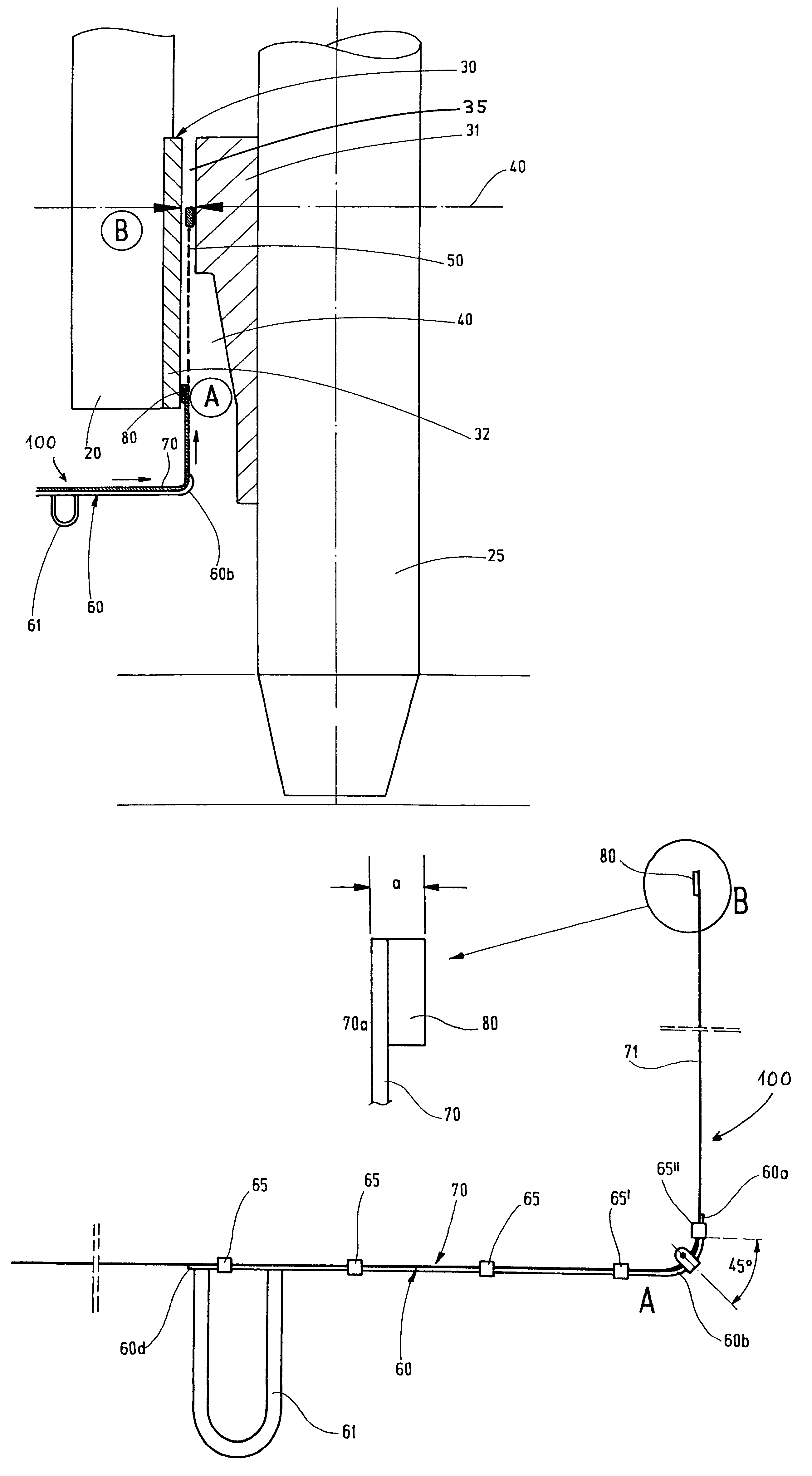
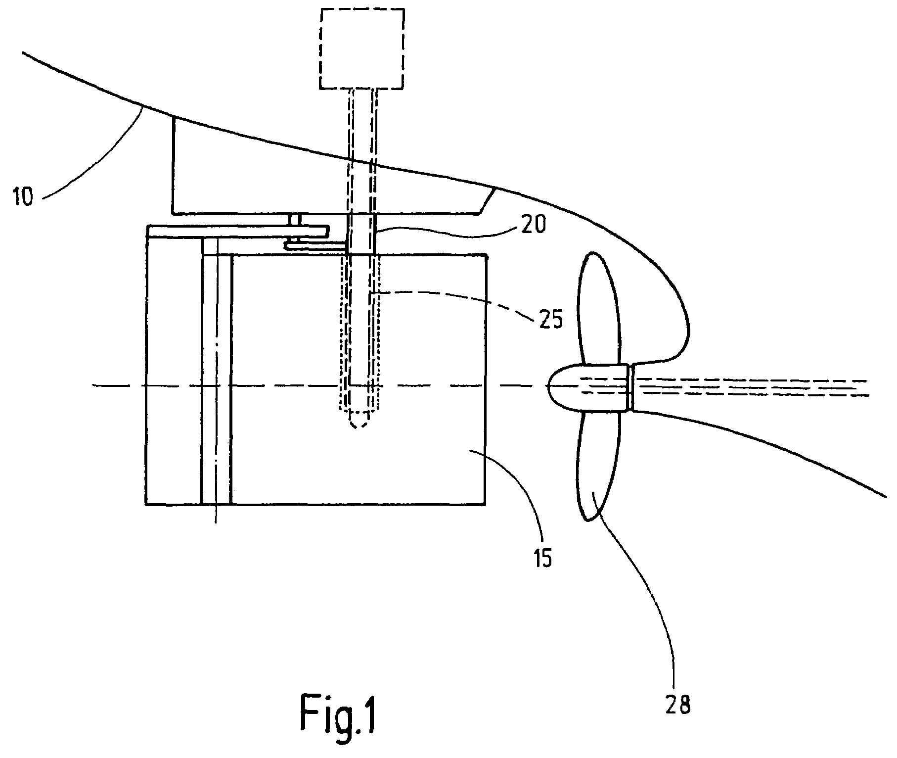
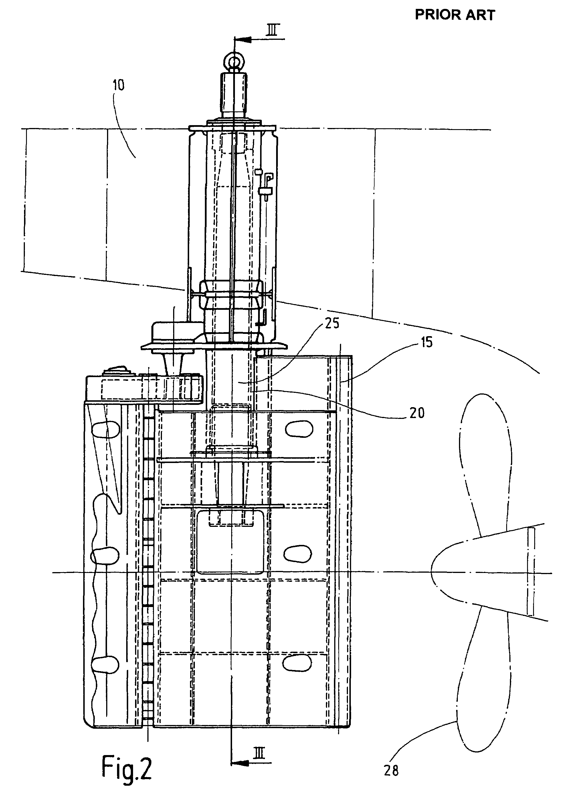
[0031]For the form of embodiment shown in FIGS. 1, 2, 3 and 4 a body of a ship is indicated by 10, a rudder blade of a rudder by 15, a rudder trunk by 20 and a rudder shaft by 25.

[0032]The rudder trunk 20, configured as a cantilever, is connected securely at its upper end 20a to the body of the ship indicated by 10 which extends in the lengthwise direction of the rudder trunk and which accommodates the rudder shaft 25. The rudder trunk 20 is guided into the rudder blade 15, which is securely connected to the free lower end of the rudder shaft 25 that is guided through the internal bore of the rudder trunk 20.

[0033]A propeller 28 relates to the rudder blade 15 of the rudder (FIGS. 1 and 2). As FIG. 14 shows at least one opening 17 is provided in the outer wall 16 of the rudder blade 15.

[0034]For the support of the rudder shaft 25 in the rudder trunk 20 a bearing 30 is provided in the lower region of the rudder shaft 25, the bearing being made up from an outer bearing located on the r...


PUM


Abstract

A device (100), for the checking and measurement of the journal bearing clearance between the outer bearing on the rudder shaft (25) of a rudder for water-borne craft and the inner bearing (32) on the rudder trunk (20) corresponding with the outer bearing (31), is characterized by a measurement rail (70) made of a springy elastic material having internal stiffness, which can be introduced by means of a guide rail (60), provided with a grip-type handle (61), into the gap between the outer bearing and the inner bearing and hence into the clearance measurement region, with a measurement probe (80) located at its free end (70a) for the clearance width measurement, wherein the measurement rail (70) with the measurement probe (80) with a prescribed thickness (a) are exchanged for measurement rails with measurement probes with other thicknesses until the achievement of an agreement of the clearance width with the thickness of a measurement rail (70) with the measurement probe (80).

Description

BACKGROUND OF THE INVENTION[0001]The invention concerns a device for the checking and measurement of the journal bearing clearance on the rudder shaft of a rudder for water-borne craft and the inner bearing on the rudder trunk corresponding with the outer bearing.PRIOR ART[0002]The clearance in the journal bearing region between the rudder shaft of a rudder for water-borne craft and the rudder trunk is subject to regular checks in which the rudder shaft is subjected to swivelling movements about its lengthwise axis, and in which the residual clearance is then measured. These checking measurements of the clearance are undertaken on ships that are lying in dock. An underwater check by divers on ships that are on the water is not possible.[0003]The object of the present invention is to create a device for the checking and measurement of the journal bearing clearance for rudders of water-borne craft that can be used underwater so that divers can undertake the check and the measurement o...

Claims


Application Information

Patent Timeline
Patent Type & Authority Patents(United States)
IPC IPC(8): G01B3/00G01M99/00
CPCB63B3/40B63H25/38B63H25/52G01B5/146
Inventor KLUGE, MATHIASPLAPPERT, DIETER
Owner BECKER MARINE SYST
Why Eureka
Try Eureka