Self-anchoring device with force amplification

a self-anchoring device and force amplification technology, which is applied in the direction of drilling pipes, drilling casings, and accessories for wellbores, etc., can solve the problems of limited power downhole, insufficient gravity to move instruments to the depths, and less power available for tractors employing active grips, so as to reduce the potential for grip damage to the formation

Active Publication Date: 2009-04-14
SCHLUMBERGER TECH CORP
View PDF49 Cites 47 Cited by
  • Summary
  • Abstract
  • Description
  • Claims
  • Application Information

AI Technical Summary

Benefits of technology

[0009]Embodiments of the present invention relate to downhole tools having passive grips that selectively grip or release a wellbore or casing wall over a large contact area, the tools being suitable for use in conveying logging tools in a well or perform various mechanical services such as opening valves, shifting sleeves, drilling, cleaning, and other mechanical services in a wellbore. The invention is generally applicable in downhole tools that need to be anchored with respect to their surroundings in order to perform various measurements and particularly applicable for use in downhole tractors and mechanical services tools. Potential for grips to damage the formation is reduced by the large contact area of the present invention. Some embodiments of the present invention also prevent any relative motion between the tool and the well bore in both uphole and downhole directions by gripping in a bi-directional manner.

Problems solved by technology

In horizontal or highly deviated wells, however, gravity is frequently insufficient to move the instruments to the depths to be logged.
The availability of power downhole is limited by the necessity to communicate through a long logging cable.
Since part of the power is used for actuating the grip, tractors employing active grips tend to have less power available for moving the tool string along the well.
Thus, an active grip is likely to decrease the overall efficiency of the tractor tool.
Another disadvantage of active grips is the relative complexity of such device and hence the risk of lower reliability.
One disadvantage of these passive grip mechanisms is that the cams exert very high contact stresses on the well walls.
In open hole wellbores having relatively soft formations, such high contact stress passive grip mechanisms may be unsuitable as they may damage the formation.

Method used


Image

  • Self-anchoring device with force amplification
  • Self-anchoring device with force amplification
  • Self-anchoring device with force amplification

Examples


Embodiment Construction

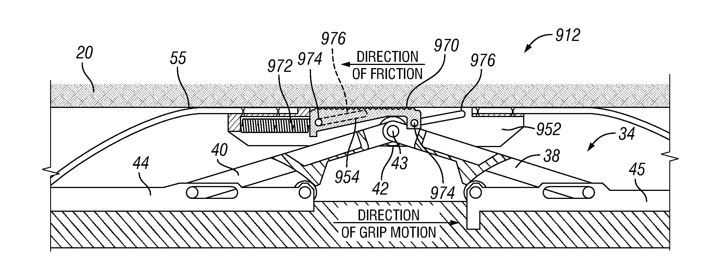
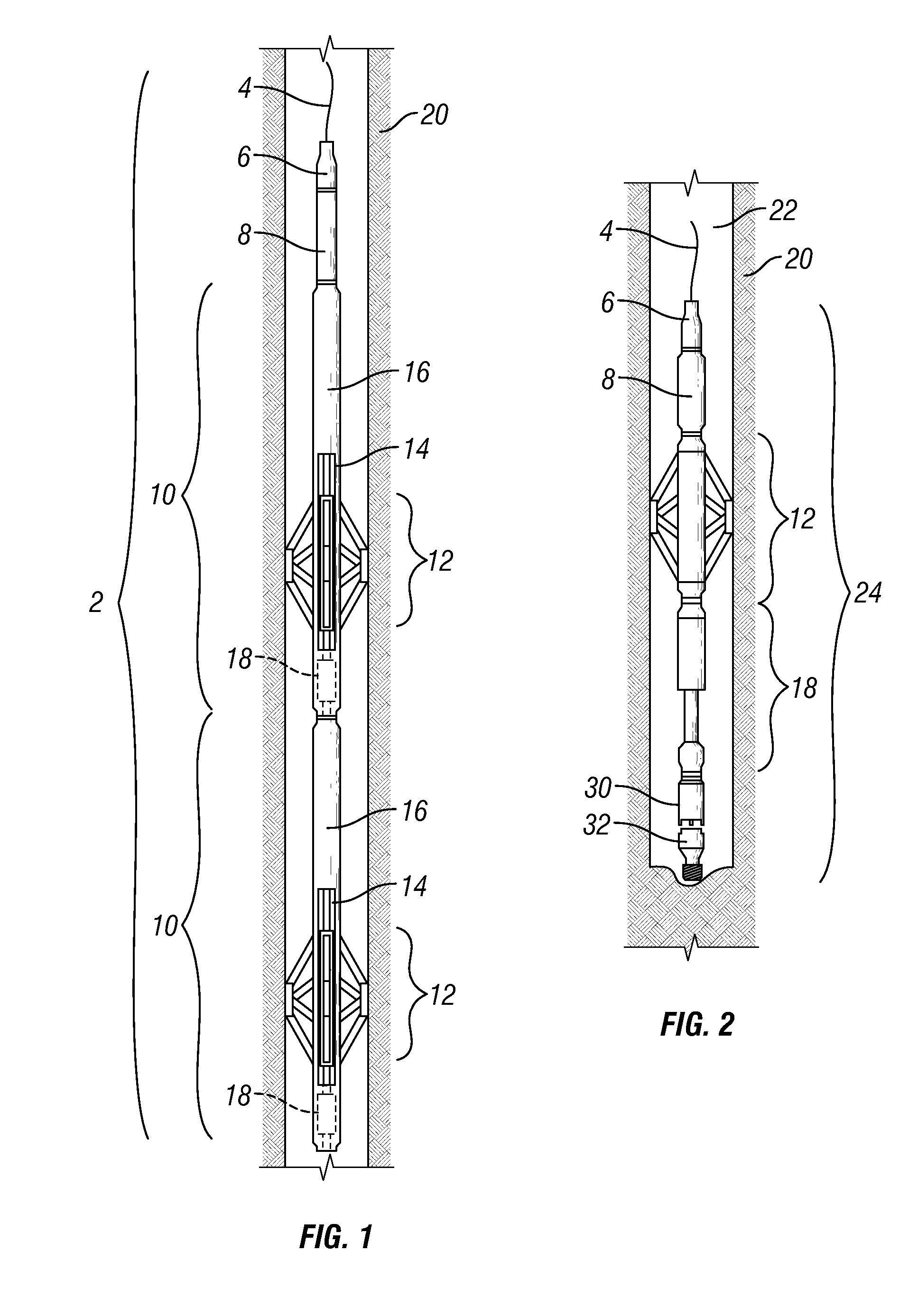
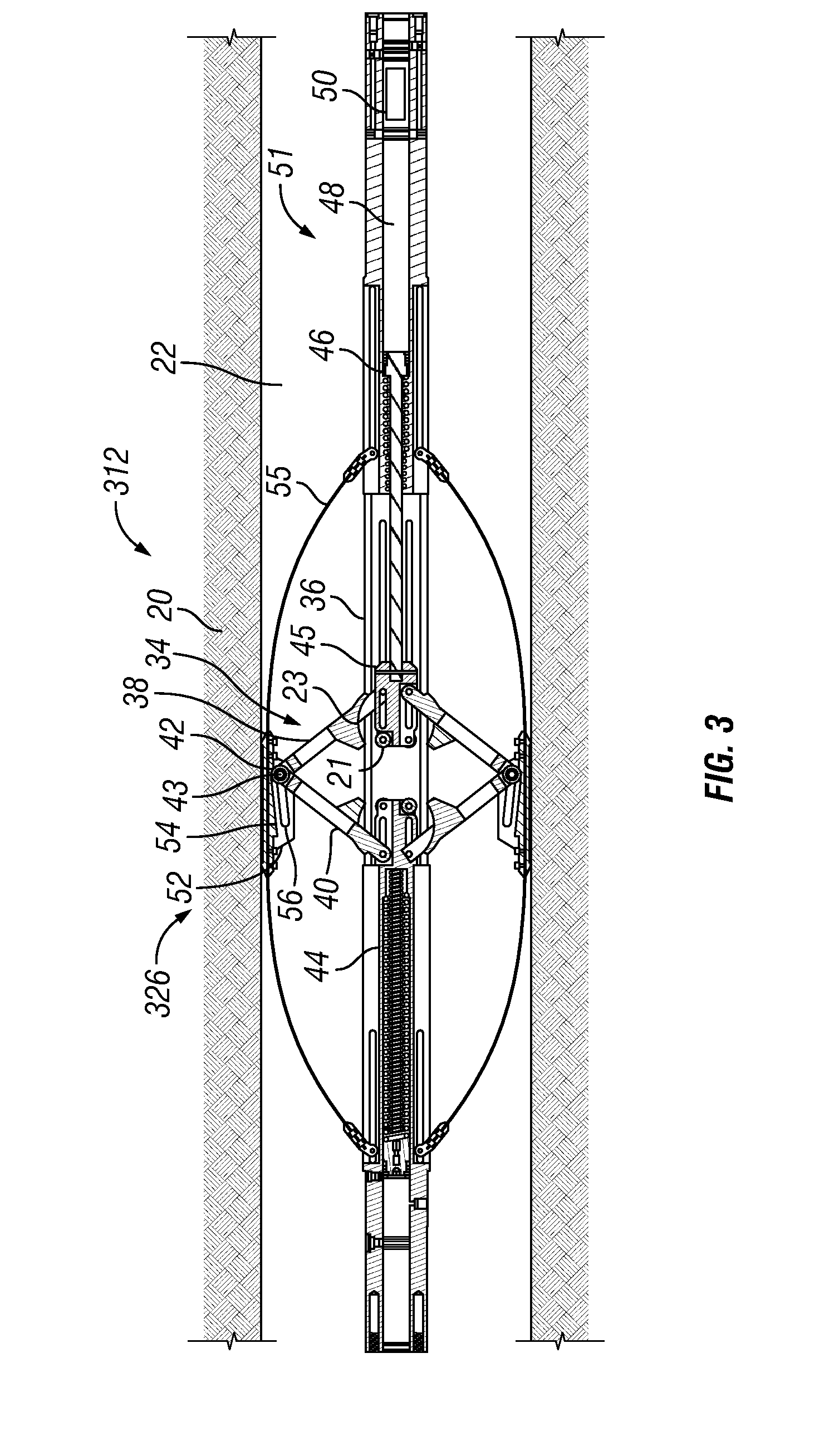
[0022]As shown in FIGS. 1-11, embodiments of the present invention are directed to a grip assembly that uses a force applied in one direction to generate a much larger force in another direction, the latter being used to anchor the grip assembly with respect to its surroundings or to create traction. In one embodiment a grip assembly 12 according to the present invention is incorporated into a downhole tractor assembly 2, such as that shown in FIG. 1. Note that in the accompanying figures, for vertically oriented figures the uphole direction is upwards and the downhole direction is downwards; and for horizontally oriented figures the uphole direction is to the left and the downhole direction is to the right. Also note that downhole tools, incorporating the present invention therein, as depicted and described herein may be used in vertical wells, horizontal wells and highly deviated wells.

[0023]Referring again to FIG. 1, the depicted tractor assembly 2 includes a logging cable 4, a c...


PUM


Abstract

A downhole tool is provided that includes a grip assembly for contacting a well formation. The grip assembly includes a gripper body; and a centralizer that is attached to and radially expandable with respect to the gripper body and that has a geometry which is lockable by a locking device. The grip assembly also includes a force amplifier in force transmitting relation with the centralizer, wherein the force amplifier transfers a force in a first direction to a much larger force in a second direction when the centralizer is locked by the locking device.

Description

CROSS-REFERENCE TO RELATED APPLICATION[0001]This application claims priority under 35 U.S.C. 119(e) to U.S. Provisional Application Ser. No. 60 / 771,659, filed on Feb. 9, 2006, which is incorporated herein by reference.FIELD OF THE INVENTION[0002]The present invention relates generally to a grip assembly that uses a force applied in one direction to generate a much larger force in another direction, the latter being used to anchor the grip assembly with respect to its surroundings or to create traction. More specifically, the invention relates to tools that may be used to convey items in a well or perform various mechanical services in a wellbore.BACKGROUND OF INVENTION[0003]Once a well is drilled, it is common to log certain sections of it with electrical instruments. These instruments are sometimes referred to as “wireline” instruments, as they communicate with the logging unit at the surface of the well through an electrical wire or cable with which they are deployed. In vertical ...

Claims


Application Information

Patent Timeline
Patent Type & Authority Patents(United States)
IPC IPC(8): E21B23/02
CPCE21B4/18E21B23/14E21B17/1021
Inventor SHEIRETOV, TODOR K.CHILCOAT, DWIGHT C.EWAN, ROBIN A.ROY, CARL JBILLINGHAM, MATTHEWAGUIRRE, FRANZ
Owner SCHLUMBERGER TECH CORP
Why Eureka
Try Eureka