Articulated boom for positioning video and medical equipment in hospital operating rooms

a technology for positioning video and medical equipment in operating rooms, applied in the field of medical booms, can solve the problems of complex and expensive retrofit process, not having the requisite ceiling booms, so as to improve viewing angles, less “down time” in the operating room, and easy access

Inactive Publication Date: 2009-04-14
COMPVIEW MEDICAL
View PDF29 Cites 32 Cited by
  • Summary
  • Abstract
  • Description
  • Claims
  • Application Information

AI Technical Summary

Benefits of technology

[0006]The medical boom thus provides a number of advantages, including improved viewing angles for a more comfortable setting for the surgeon and medical staff. Since the stationary base is mounted onto the floor in an operating room, the aforementioned issues of using ceiling booms to suspend equipment is avoided. The medical boom of the present invention can also be installed in an operating room in a few days or less, resulting in less “down time” of the operating room. The stationary base can be used to house a host of electronic and medical equipment. It thus provides a centralized control station that can be readily accessed by the surgeon and medical staff. The medical boom can also be configured to deliver services, such as power and control electrical signals, gases, fluids, and fluid recovery from the patient.

Problems solved by technology

There are a number of problems, however, associated with using booms suspended from the ceiling.
As a result, operating rooms were not built with the requisite ceiling booms to suspend the equipment.
The retrofit process, however, is very complicated and expensive.
A retrofit project will therefore take at least several months and cost well into the six figure dollar amount.
Since the operating room can not be used during the construction, the retrofit process also results in a significant loss of revenue for the hospital.
With newer hospitals, the cost and expense of designing and implementing the boom system from the ceiling during construction is also considerable.

Method used


Image

  • Articulated boom for positioning video and medical equipment in hospital operating rooms
  • Articulated boom for positioning video and medical equipment in hospital operating rooms
  • Articulated boom for positioning video and medical equipment in hospital operating rooms

Examples


Embodiment Construction

[0019]The present invention will now be described in detail with reference to a few preferred embodiments thereof as illustrated in the accompanying drawings. In the following description, numerous specific details are set forth in order to provide a thorough understanding of the present invention. It will be apparent, however, to one skilled in the art, that the present invention may be practiced without some or all of these specific details. In other instances, well known operations have not been described in detail so not to unnecessarily obscure the present invention.

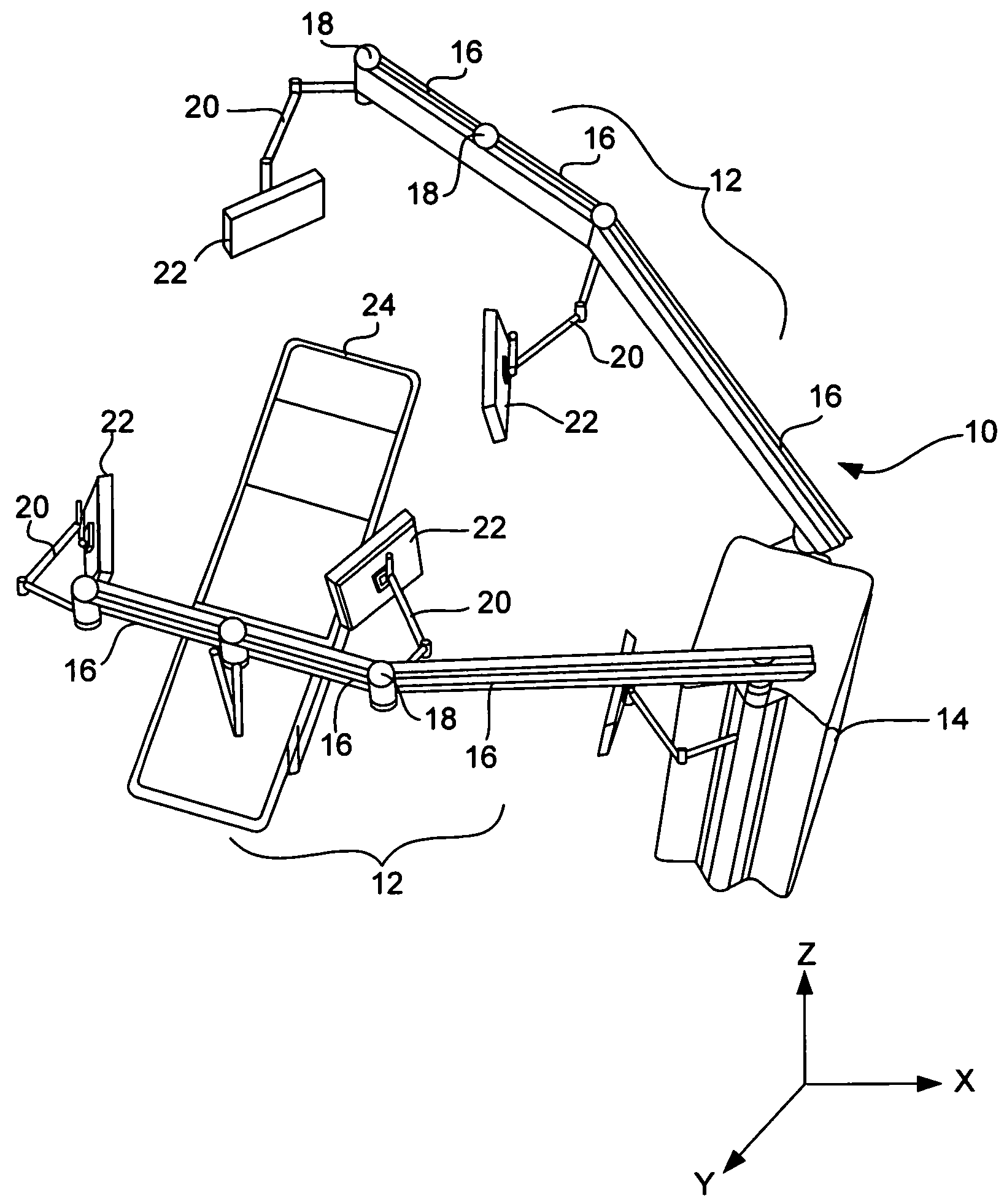
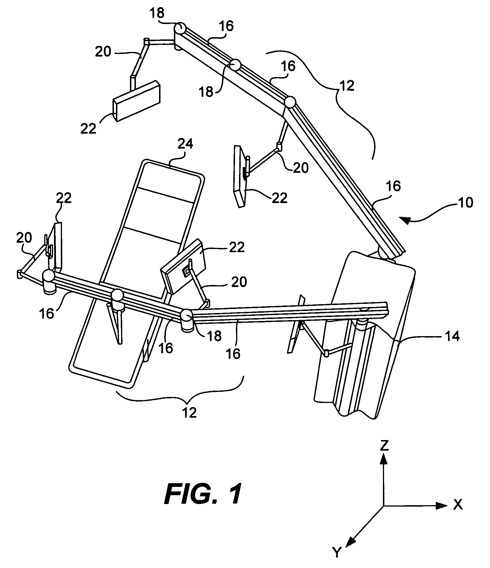
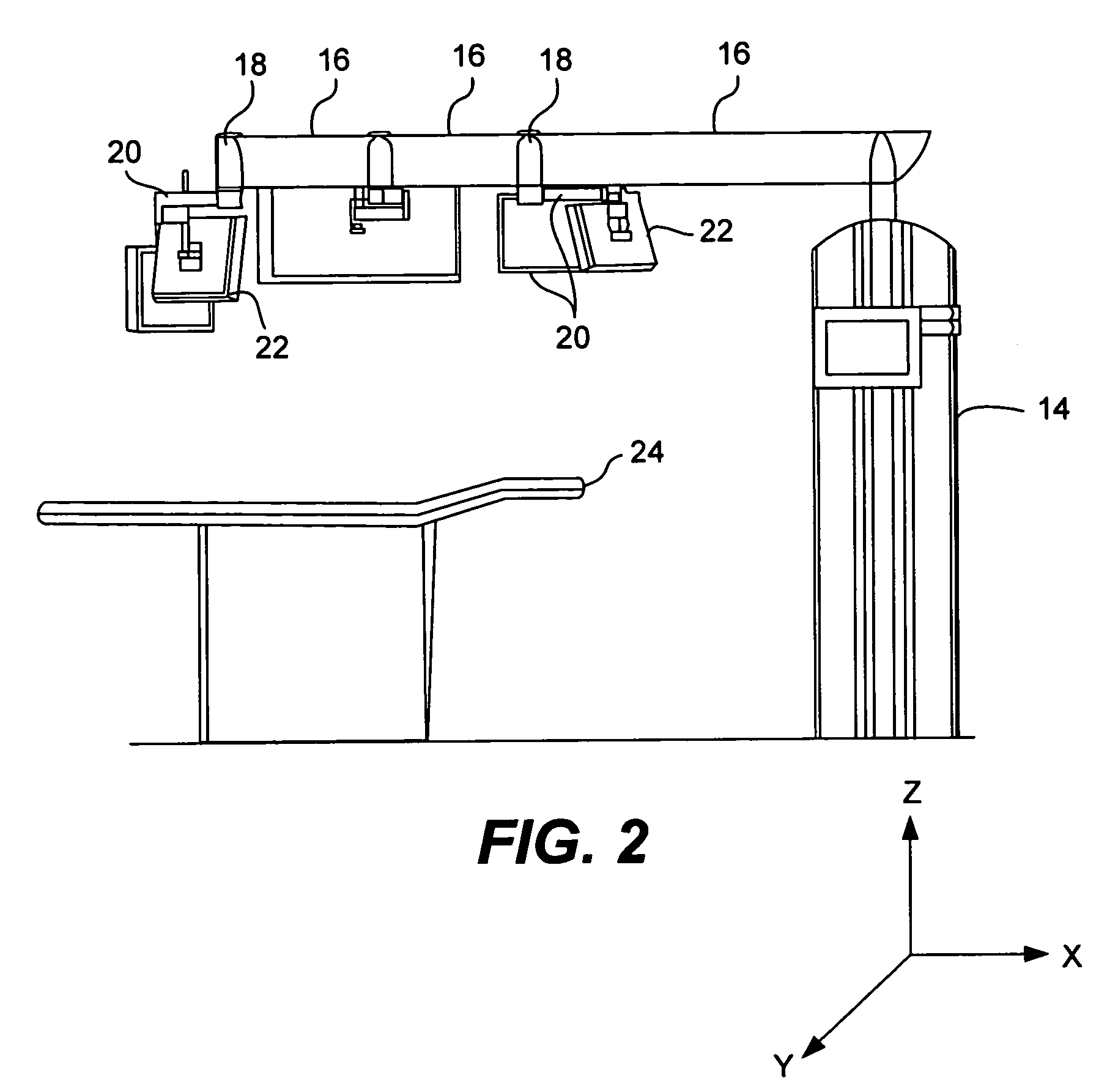
[0020]Referring to FIG. 1, a perspective view of the medical boom in an operating room according to the present invention is shown. The medical boom 10 includes one or more articulated boom arms 12 mounted onto a stationary base 14. Each articulated boom arm 12 is made from a number of arm segments 16 held together by joints 18. One or more articulated appendage arms 20 are also attached to each articulated boom arm...


PUM


Abstract

The present invention is directed to a stationary medical boom that can be easily installed on the floor of an existing operating room and that has one or more articulated arms used to position audio, video and medical equipment over an operating table in an operating room. The boom includes a stationary base configured to be attached to the floor of the operating room. One or more articulated boom arms are supported by the stationary base and extend out over the operating table. Articulated appendage arms, extending from the boom arms, are configured to support the audio, video and other medical equipment used in the operating room in the vicinity of the operating table. Both the articulated boom arm and the articulated appendage arm can be moved in either the X and / or Y directions. Consequently, the equipment supported by the appendage arm can be moved in virtually any position around the operating table.

Description

FIELD OF THE INVENTION[0001]The present invention relates generally providing medical personal access to audio, visual and medical equipment in a hospital operating room, and more particularly, to a medical boom that provides a universal connection point for needed services in the operating room, including audio and video inputs and outputs, power, fluid delivery and recovery, and gases. The medical boom includes a stationary base with and one or more articulated arms supported by the base. The articulated arms provide 360 degree positioning of audio, visual and medical equipment around the operating field.BACKGROUND[0002]State of the art hospital operating rooms now contain a wide variety of audio, visual and technology tools, such as video cameras, video recorders, microphones and voice recorders, video guided ultrasound imaging systems, lasers, cytoscanners, etc. With delicate surgery for example, a 3D video camera may be placed in or above the surgical area of the patient. The i...

Claims


Application Information

Patent Timeline
Patent Type & Authority Patents(United States)
IPC IPC(8): A47F5/00A47F7/00
CPCA61B19/0248A61B19/26Y10S248/919Y10S248/921Y10S248/917A61B50/10A61B90/50
Inventor WHITE, PAULVOLLUM, LARRY
Owner COMPVIEW MEDICAL
Why Eureka
Try Eureka