Suction disc unit

a technology of suction discs and discs, which is applied in the direction of shaving accessories, other domestic objects, machine supports, etc., can solve the problems of reducing the pushing distance, and achieve the effect of increasing the suction

Inactive Publication Date: 2009-04-14
COMART CORP
View PDF8 Cites 24 Cited by
  • Summary
  • Abstract
  • Description
  • Claims
  • Application Information

AI Technical Summary

Benefits of technology

[0010]In view of the above problems resided in the prior arts, the inventor of the present invention provides a suction disc unit of which the suction effect is increased.

Problems solved by technology

The prior arts using a spring to remove air is worth being taken for reference, however, they still have the problems such as being cumbersome in assembling and having elastic fatigue, the pushing force of each of the springs is inadequate, the distance of pushing will be reduced by such elastic fatigue .

Method used


Image

  • Suction disc unit
  • Suction disc unit
  • Suction disc unit

Examples


first embodiment

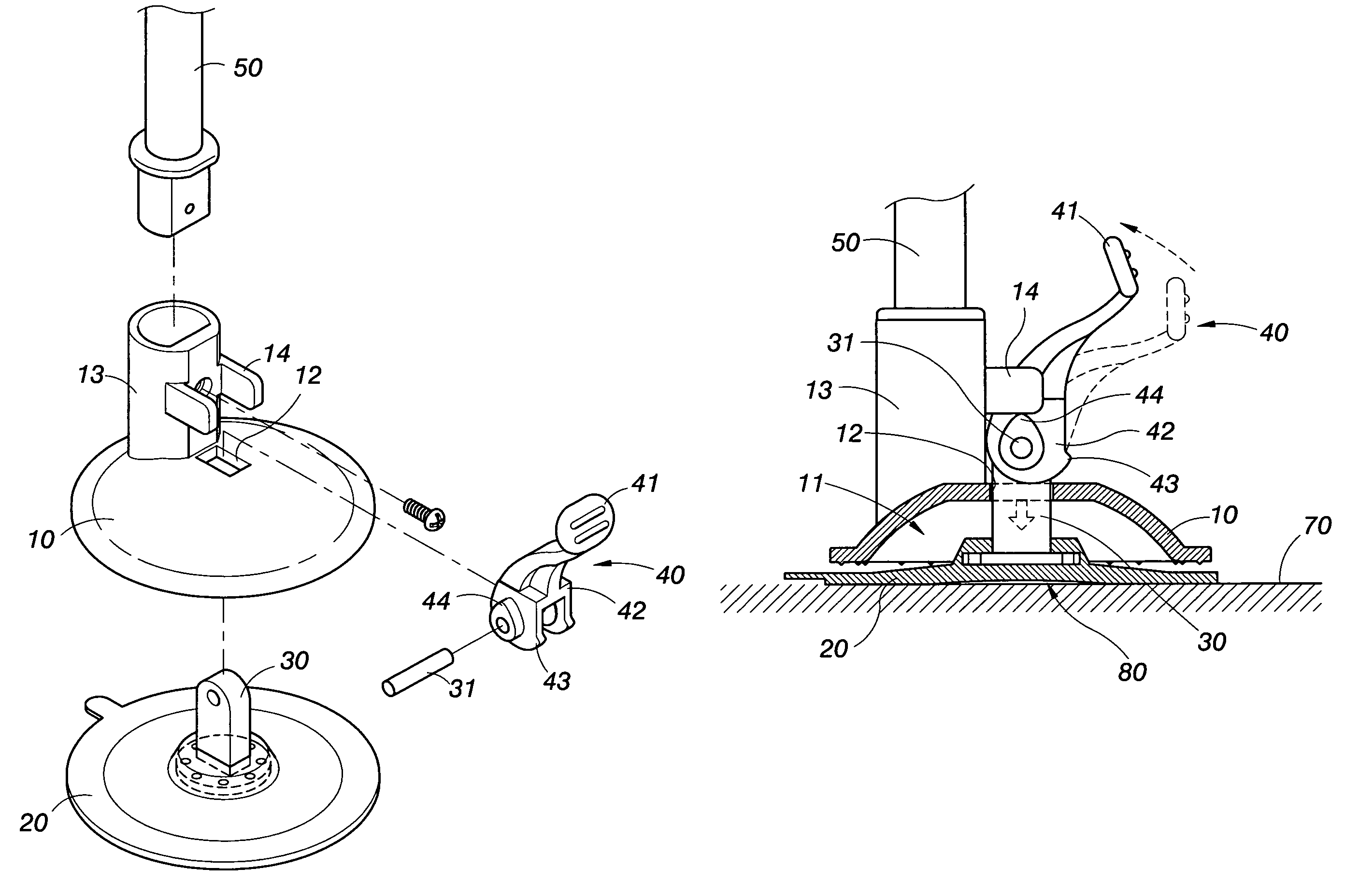
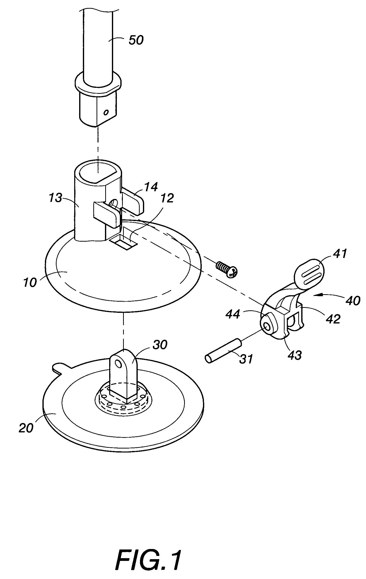
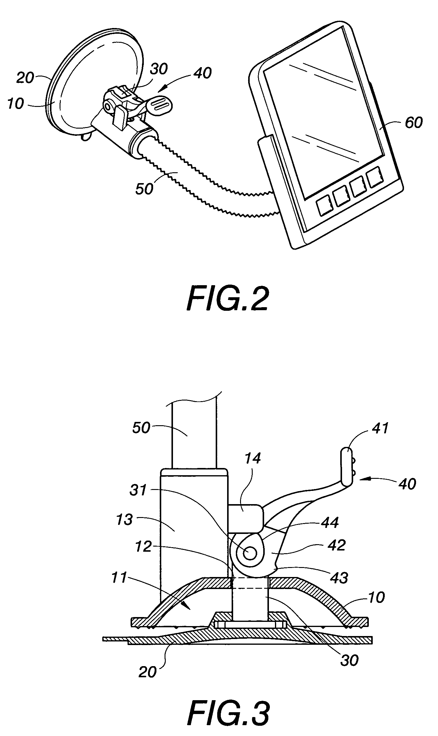
[0022]Referring firstly to FIGS. 1 and 2 which are respectively perspective views before and after assembling of the present invention; wherein the suction disc unit of the present invention comprises the main members including a pressing lid 10, a suction disc 20, a link 30 and a pressing rod 40; and a connecting member 50 is provided for mounting an article 60 such as a PDA, a GPS, a mobile phone, an A / V equipment or some other instrument, meter etc.

[0023]Referring simultaneously to FIGS. 1 and 3, wherein FIG. 3 is a sectional schematic view of the first embodiment of the present invention; the pressing lid 10 has in its inner side a receiving space 11, the pressing lid 10 is provided centrally thereof with a hole 12 and is provided on its outer side with a connecting seat 13, the connecting seat 13 is provided thereon at least with a protruding stopper 14 that can be integrally formed with the connecting seat 13; the connecting seat 13 is used for positioning the connecting membe...

second embodiment

[0028]As shown in FIG. 6 which is a sectional schematic view of the present invention, in this embodiment, the pressing end 41 is in the form of a hanging member such as a hook or a ring etc., so that the pressing end 41 can be used for hanging an article, while the stopper 14 can be fixed directly on or integrally formed with the pressing lid 10.

third embodiment

[0029]As shown in FIG. 7 which is a sectional schematic view of the present invention, in this embodiment, the pivotally connecting end 42 is in the form of a twin cam, the first eccentric protruding portion 43 and the second eccentric protruding portion 44 are directly formed on the twin cam, thereby during the process of pivoting of the pressing rod 40, as is stated above, the first eccentric protruding portion 43 abuts downwards against the pressing lid 10, and the second eccentric protruding portion 44 abuts against the protruding stopper 14, by these two actions of alternate pushing by abutting, the action of suction is effected.

Effects

[0030]The present invention at least has the following advantages:[0031]1. The present invention can effectively reduce the residual air in the gap between the suction disc and the smooth surface, so that when the gap between the suction disc and the smooth surface expands, the air pressure in the gap is much lower than that of the surrounding at...


PUM


Abstract

A suction disc unit, especially a suction disc unit that can be adsorbed on a smooth surface to support a hung article, it comprises a pressing lid, a suction disc, a link and a pressing rod; wherein the pressing rod at least has a first eccentric protruding portion and a second eccentric protruding portion; when the pressing lid is pulled up to make abutment of the suction disc against the smooth surface by pushing of the pressing rod, the air in the gap between the suction disc and the smooth surface is removed as much as it can; when the pressing rod is pressed down, the pressing lid abuts against the periphery of the suction disc, and the central portion of the suction disc is pulled up tight, the air pressure in the gap is much lower than that of the atmosphere to thereby induce a strong suction force, and thereby to increase the bearing strength of the suction disc unit.

Description

BACKGROUND OF THE INVENTION[0001]1. Field of the Invention[0002]The present invention is related to a suction disc unit that can be adsorbed on a smooth surface to support a hung article, and especially to an improved design of suction disc for increasing adsorbing force and thus increasing supporting force.[0003]2. Description of the Prior Art[0004]A suction disc unit mainly is used to be adsorbed on a plain surface to support a hung article. Taking the U.S. Pat. Nos. 6,234,435 and 6,749,160 as examples, wherein a suction disc unit can be adsorbed on a piece of glass of a car, the suction disc unit is provided with a supporting rod and a receiving seat etc. to support a PDA or GPS etc. And as is stated in the U.S. Pat. No. 6,550,735, hanging hooks are provided on a suction disc unit, thereby a suction disc can be adsorbed on a smooth surface such as a piece of tile or glass to hang at will thereon an article of daily necessities such as a tower, a suit of clothes etc.[0005]The abov...

Claims


Application Information

Patent Timeline
Patent Type & Authority Patents(United States)
IPC IPC(8): A45D42/14
CPCF16B47/006
Inventor LIU, SU-WEI
Owner COMART CORP
Why Eureka
Try Eureka