Radio frequency ablation system with integrated ultrasound imaging

a radio frequency ablation and ultrasound imaging technology, applied in the field of radio frequency ablation systems with integrated ultrasound imaging, can solve the problems of difficult to insert a needle electrode or other energy delivery device therein, add more complexity to the operation, and require additional incisions

Inactive Publication Date: 2009-04-14
BOSTON SCI SCIMED INC
View PDF8 Cites 67 Cited by
  • Summary
  • Abstract
  • Description
  • Claims
  • Application Information

AI Technical Summary

Problems solved by technology

However, as many tumors and fibroids are loosely held in place by ligaments and other structures, movement of the target tissue mass may make it difficult to insert a needle electrode or other energy delivery device thereinto.
Grasping devices and anchors may be used to immobilize the target tissue mass while an electrode is inserted thereinto, but these procedures add more complexity to the operation and may require additional incisions.
However, the field of view of these vision systems is small and may be insufficient to properly perform and assess the effectiveness of the treatment.
Conventional vision systems may also have difficulty in facilitating the positioning of the electrodes within the tissue, as the tissue itself obscures viewing of the electrodes.

Method used


Image

  • Radio frequency ablation system with integrated ultrasound imaging
  • Radio frequency ablation system with integrated ultrasound imaging
  • Radio frequency ablation system with integrated ultrasound imaging

Examples


Embodiment Construction

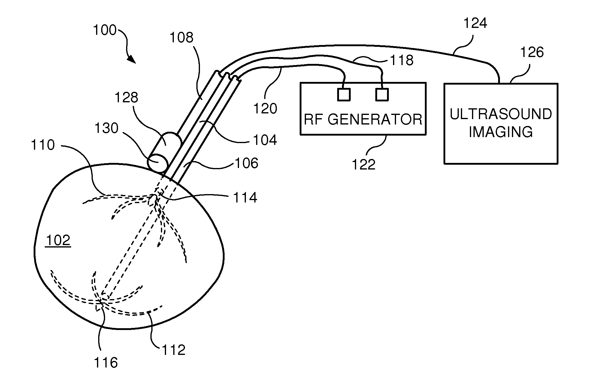
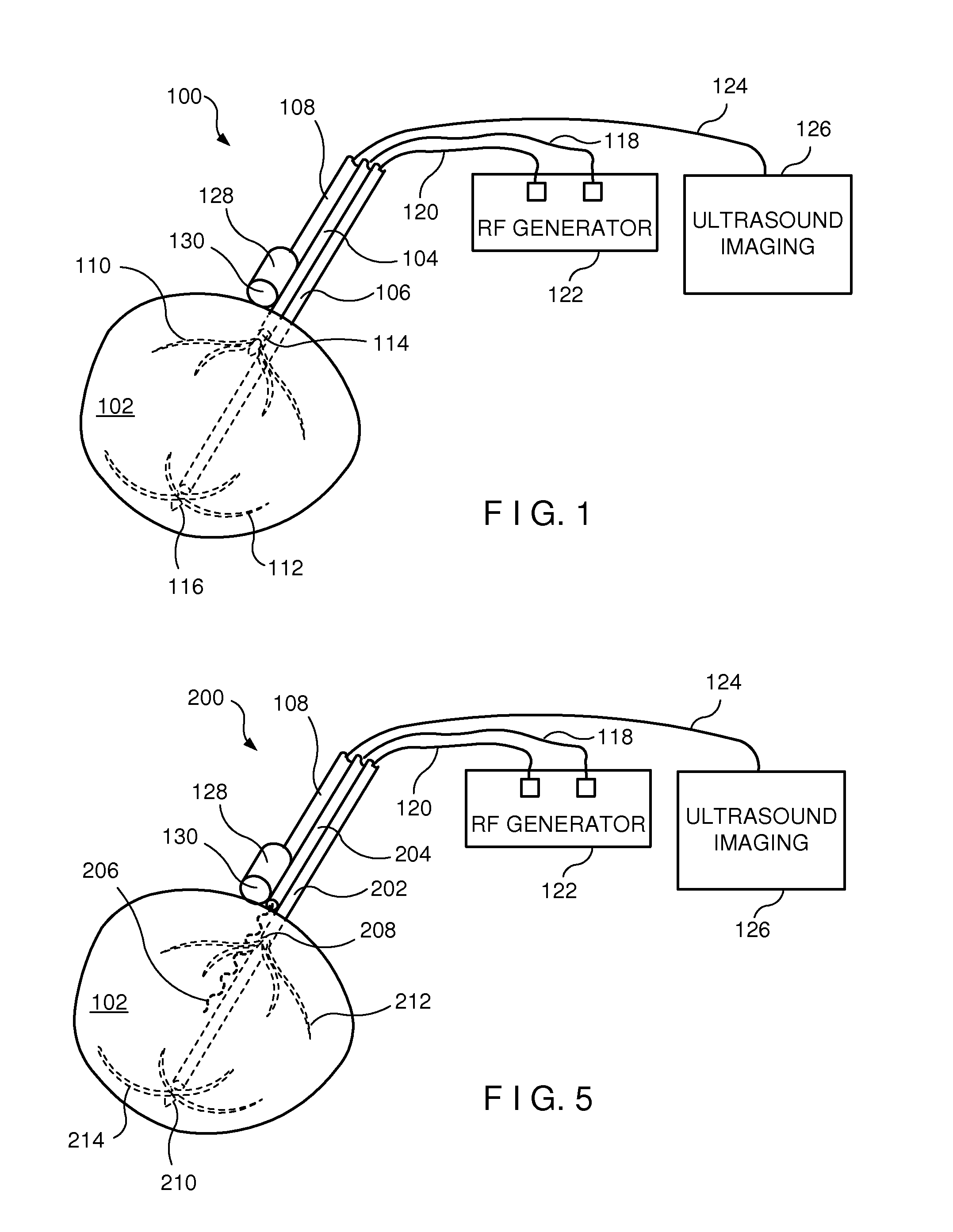
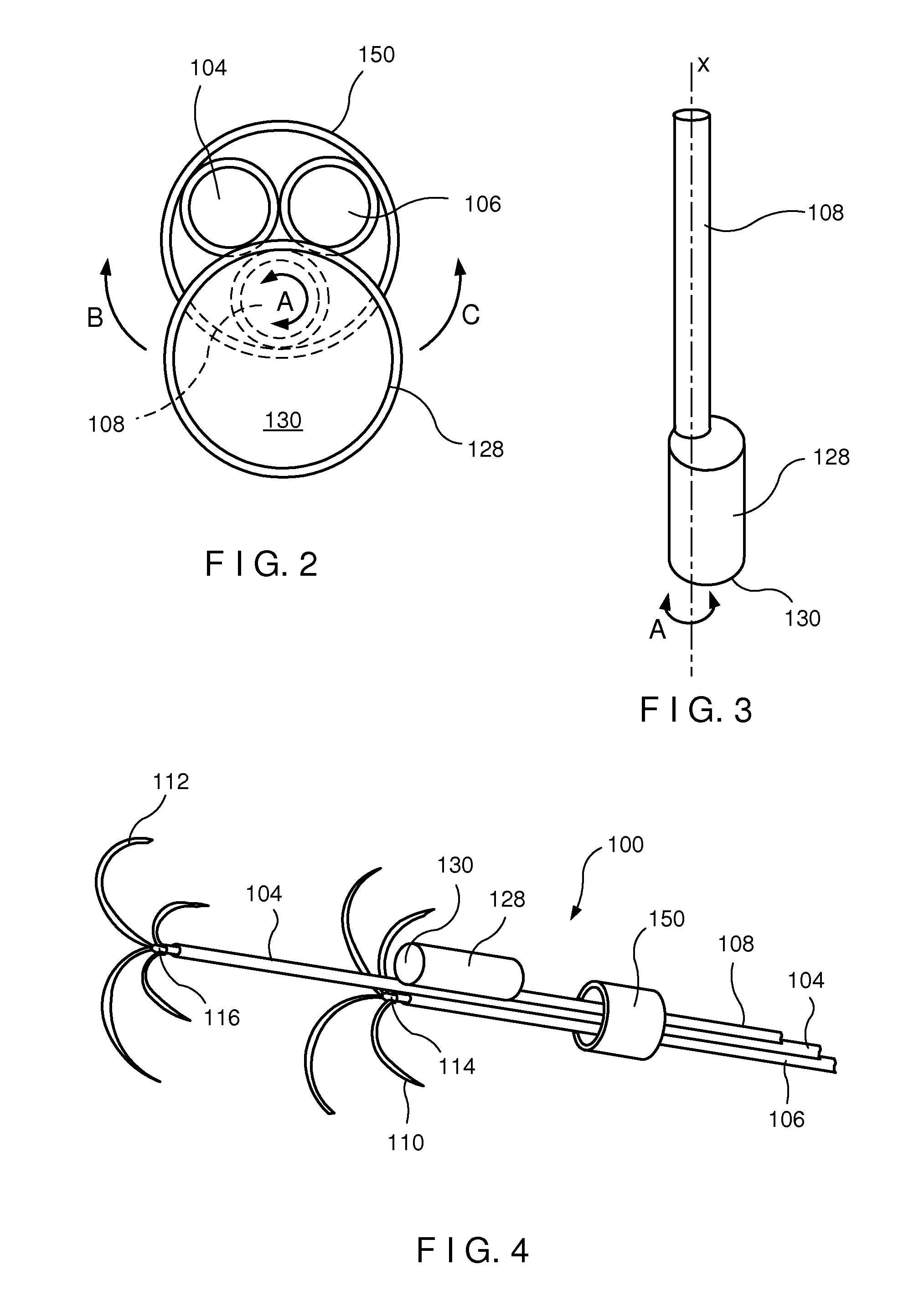
[0013]The present invention may be further understood with reference to the following description and the appended drawings, wherein like elements are referred to with the same reference numerals. The present invention relates to devices for treating tissue such as fibroids, tumors and other tissue masses by applying electric energy through electrodes inserted into a target tissue mass. The present invention also relates to devices used to ablate tissue to reshape an organ.

[0014]In one embodiment, energy delivery elements of the apparatus according to the present invention are deployable from a single medical instrument. For example, such a single instrument may include two tined arrays or one tined array and one clamp which are placed on or within the target tissue mass to treat the target tissue. In other embodiments, the instrument may include devices for grasping and holding in place the target tissue mass, minimizing the minimum number of incisions and medical personnel require...


PUM


Abstract

A tissue ablation system comprises a first electrode assembly adapted for insertion into a target tissue mass within a body, the first electrode assembly including a first electrode coupled to a source of RF energy in combination with an ultrasound imaging probe movably coupled to the first electrode assembly for insertion with the first electrode assembly to a desired location relative to the target tissue mass, the probe being movable relative to the first electrode assembly between an insertion configuration in which a distal end of the probe covers a distal end of the first electrode assembly and a deployed configuration in which the distal end of the first electrode assembly is uncovered. A method of ablating target tissue within a body comprises placing a distal dome of an ultrasound imaging probe in overlying alignment with a first cannula of an RF ablation device and inserting the probe and the RF ablation device through a lumen of an insertion device to a desired location adjacent to a target tissue mass in combination with moving the distal dome away from a distal end of the first cannula to expose a distal end thereof, inserting the distal end of the first cannula into the target tissue mass to position a first electrode of the RF ablation device at a first desired location within the target tissue mass, obtaining an image of the target tissue mass and the first electrode via the probe and applying RF energy to the target tissue mass via the first electrode.

Description

BACKGROUND[0001]Fibroids, tumors and other tissue masses are often treated by ablation. In many cases, local ablation of the diseased tissue is carried out by inserting a therapeutic device into the tissue and carrying out therapeutic activity designed to destroy the diseased cells. For example, electrical energy may be applied to the affected area by placing one or more electrodes into the affected tissue and discharging electric current therefrom to ablate the tissue. Alternatively, tissue may be ablated cryogenically, by applying heat or chemically by injecting fluids with appropriate properties to the target tissue.[0002]However, as many tumors and fibroids are loosely held in place by ligaments and other structures, movement of the target tissue mass may make it difficult to insert a needle electrode or other energy delivery device thereinto. Grasping devices and anchors may be used to immobilize the target tissue mass while an electrode is inserted thereinto, but these procedu...

Claims


Application Information

Patent Timeline
Patent Type & Authority Patents(United States)
IPC IPC(8): A61B18/14A61B8/12
CPCA61B18/1477A61B2018/143A61B2018/1432A61B2019/5276A61B2019/5278A61B2090/3782A61B2090/378
Inventor SLOAN, TODDOSTROVSKY, ISAACMCINTYRE, JON T.
Owner BOSTON SCI SCIMED INC
Why Eureka
Try Eureka