Tilted edge for optical-transfer-function measurement

a technology of optical transfer function and tilting edge, which is applied in the direction of measurement devices, structural/machine measurement, instruments, etc., can solve the problems of data stitching challenges, aliasing of imaged signals, narrow detector field of view, etc., and achieves a quick and practical way of calculation

Inactive Publication Date: 2009-04-14
EDMUND OPTICS
View PDF5 Cites 5 Cited by
  • Summary
  • Abstract
  • Description
  • Claims
  • Application Information

AI Technical Summary

Benefits of technology

[0014]The invention lies in carrying out a measurement of the optical transfer function of an optical element in conventional manner using a traditional edge method, but also tilting the edge with respect to the edge-response detection line. The effect of the tilt is to stretch out the edge response so that fine details can be detected even operating at a spatial frequency (measured in the global coordinate system) below the Nyquist limit of the detector. The tilt, in essence, produces a re-sampling of the edge at a spatial frequency higher than the Nyquist limit (measured in the local—with respect to the edge—coordinate system), thereby avoiding aliasing of the signal even while sampling at a below-Nyquist rate.
[0015]According to an important aspect of the invention, multiple targets are used, each corresponding to a sub-region (referred to as a “field point” in the art) of the field of view of the optics being tested. Each target includes one or more tilted edges that provide a measurement for the corresponding field point of the optics. This approach enables the simultaneous characterization of the full field of view of the test optics with a single measurement without the use of a magnifying objective. The result is a rapid measurement and a simpler apparatus suitable for high-throughput testing.
[0017]According to still another aspect of the invention, the same concept may be used to characterize the quality of a sub-assembly within an imaging system, such as the lens of a camera. The invention provides a rapid and practical way to calculate the optical transfer function of the system, thereby making it possible to make adjustments in the sub-assembly (such as adjusting the focus of the lens in the camera) to meet predetermined OTF design specifications.

Problems solved by technology

Nonetheless, commercial applications often specify image quality only in terms of the system's modulation transfer function.
Therefore, since low-contrast conditions are typically not of interest, the impact of phase shifts is less significant under practical working conditions, where contrast must be high.
One of the problems consistently encountered in this type of measurement is the fact that sampling is often insufficient (that is, the detector is operated below its Nyquist limit of sampling), which produces aliasing in the imaged signal.
While effective, this solution has the drawback of narrowing the field of view of the detector, which therefore requires that a scanning mechanism be utilized to span the field of the optics being tested.
This, in turn, introduces alignment and data-stitching challenges to the process of data acquisition, in addition to the cost of the additional optics and scanning hardware.
Most importantly, the use of a microscope objective and the attendant scanning operation greatly affect the speed with which the optical transfer function of an imaging system can be measured.
While production facilities have been able to readily scale up for volume, the quality-control functions have not been able to keep pace with increased manufacturing capabilities.
Commercially available instruments for quality control are designed for expensive and relatively slow testing procedures for cost-insensitive low-volume projects.

Method used


Image

  • Tilted edge for optical-transfer-function measurement
  • Tilted edge for optical-transfer-function measurement
  • Tilted edge for optical-transfer-function measurement

Examples


Embodiment Construction

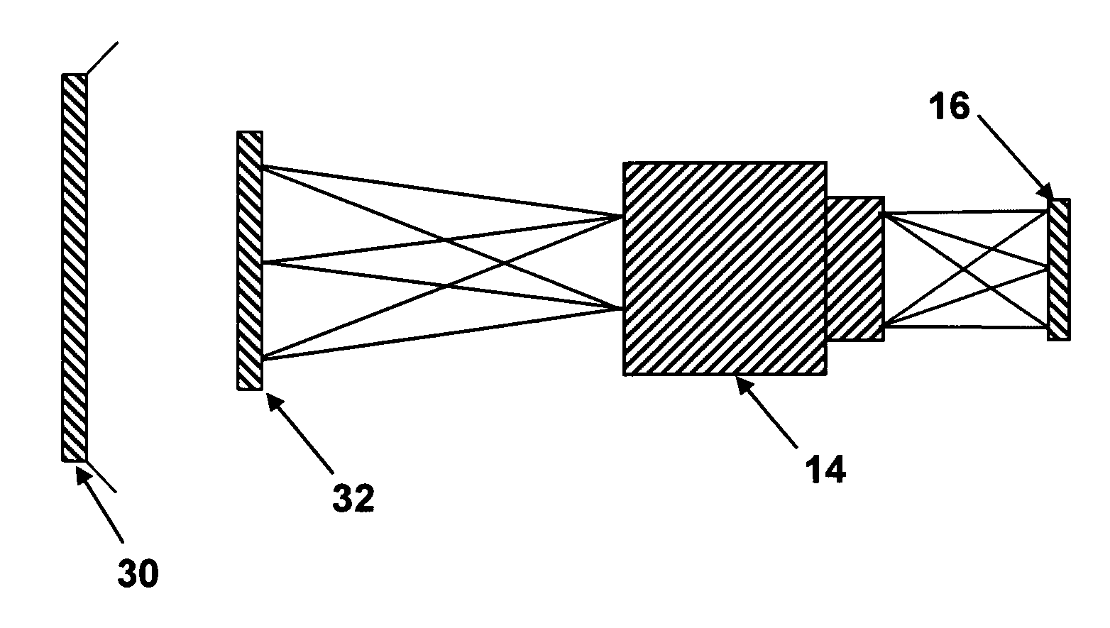
[0030]The inventive aspect of this disclosure lies in the idea of using multiple targets to measure the field of the optics being tested and tilting the edge of conventional edge-scan targets with respect to the edge-response detection line. As defined in the art, this is the line along which the contrast in the image created by the edge in the target is measured across the field of the optics being tested (or across a sub-region of the field, as the case may be). In prior-art apparatus, the edge is kept in perpendicular position with respect to the direction of the detection line. Instead, the present invention introduces an arbitrary tilt which may vary greatly over an optimal angle that depends of the geometry of the system, pixel size and shape, and similar specifications.

[0031]The tilt of the invention produces a skewed measurement and a corresponding magnification factor that can be described in terms of two analogous observations. First, the tilt of the edge effectively stret...


PUM


Abstract

The optical transfer function of imaging optics is carried out with a plurality of tilted edges with respect to the edge-response detection line. The effect of the tilt is to stretch out the edge response so that fine details can be detected even operating at a spatial frequency below the Nyquist limit of the detector. The use of multiple targets, each corresponding to a sub-region of the field of view of the optics being tested, enables the simultaneous characterization of the full field of view of the test optics with a single measurement without the use of a magnifying objective. The result is a rapid measurement and a simpler apparatus suitable for high-throughput testing. A pair of tilted edges can be used in a target to also determine the sagittal and tangential OTFs (as well as that of any other arbitrary cross-section). All of these data are acquired with a single measurement.

Description

RELATED APPLICATIONS[0001]This application is based on U.S. Provisional Application Ser. No. 60 / 570,375, filed 12 May 2004.BACKGROUND OF THE INVENTION[0002]1. Field of the Invention[0003]This invention is related in general to the field of metrology of optical lenses and electro-optic systems. In particular, the invention relates to high-throughput measurements of the optical transfer function of lenses and imaging systems.[0004]2. Description of the Related Art[0005]For the purposes of this disclosure, the term “optics” is used to designate both the field of optics and optical components or systems, as is commonplace in the art. In the field of optics, where objects are imaged by a lens or a system of lenses and the resulting images are used for further processing, it is very important that the images produced by the optics be as true as possible to the objects from which they are formed. The accuracy with which optics produce the image of an object is characterized in the art by t...

Claims


Application Information

Patent Timeline
Patent Type & Authority Patents(United States)
IPC IPC(8): G01B9/00G01M11/02
CPCG01M11/0292
Inventor SADOULET, SAMUEL P.TAYLOR, BYRON
Owner EDMUND OPTICS
Why Eureka
Try Eureka