
Hinge device

Inactive Publication Date: 2009-04-21
GM GLOBAL TECH OPERATIONS LLC
View PDF16 Cites 17 Cited by
  • Summary
  • Abstract
  • Description
  • Claims
  • Application Information

AI Technical Summary

Benefits of technology

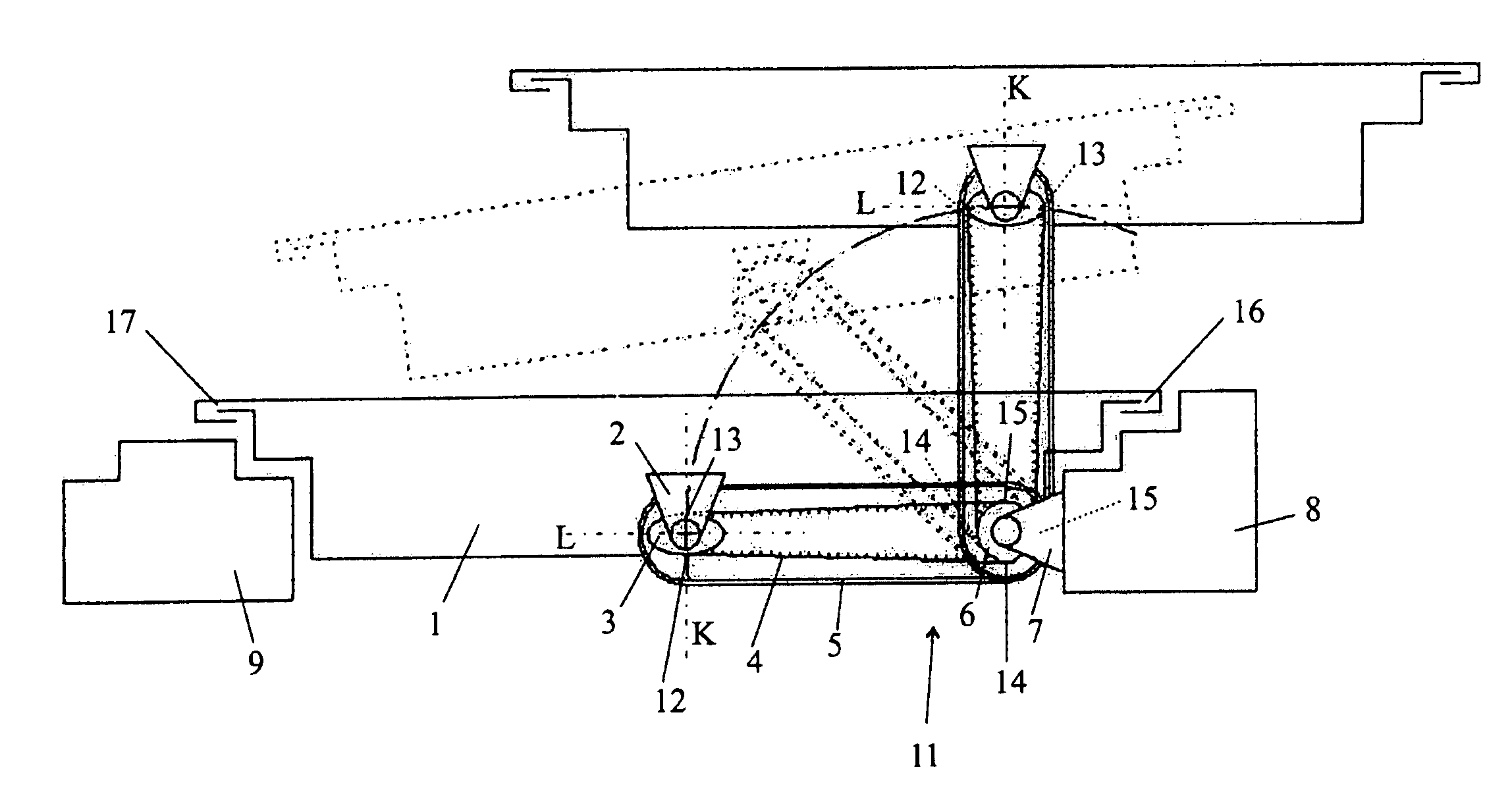
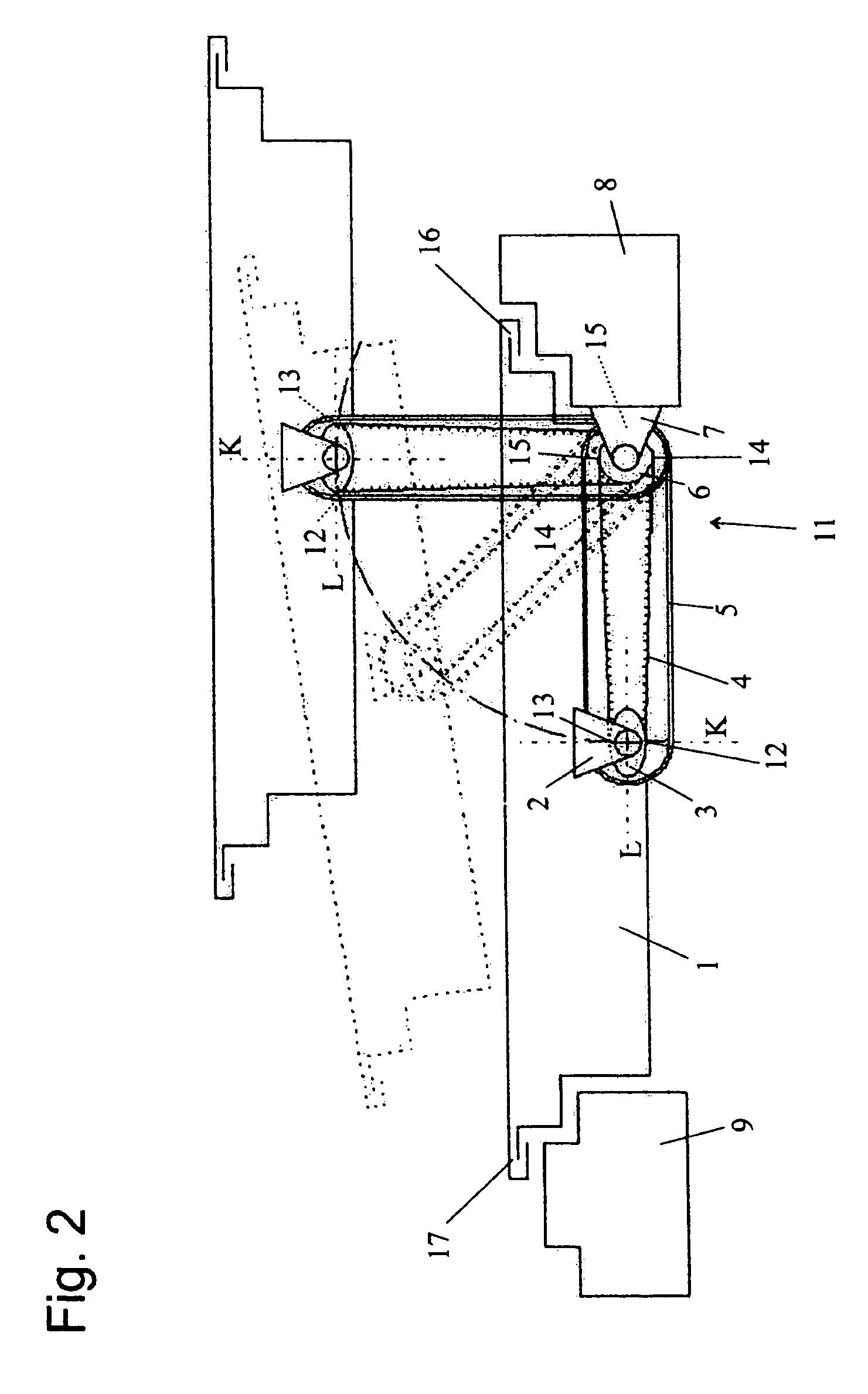
[0006]When, in the case of the moving parts, we are dealing with a door as described above, these two parallel positions can correspond to a closed door position and to an open arrested door position in which said door rests offset alongside the body, in parallel to the closed position. By virtue of having to run through a pivoted position to get from the closed position to the open parallel position, the movement involved upon closing the door is not an exact parallel translational motion so that a pressure buildup on the interior of the motor vehicle is avoided and the door can fall unobstructed into the lock. With the proper orientation of the pivoted position in terms of the relative wind, the latter exerts a force upon the door that is in the direction of the closed door; an unexpected wide open prying of the door is thus excluded.
[0010]In order to achieve a broad range of free swivel motion for the hinge device, it can be advantageous when the arm is angled and the traction belt between the belt pulleys is guided on two rollers.

Problems solved by technology

Another problem consists therein that when the door is inadvertently opened while the vehicle is being driven, the relative wind—as opposed to the conventional case in which a door is mounted to the body by a single hinge on the front door edge, relative to the direction of travel—can bear down behind the partially-opened door and pry it completely wide open.

Method used


Image

  • Hinge device
  • Hinge device
  • Hinge device

Examples


Embodiment Construction

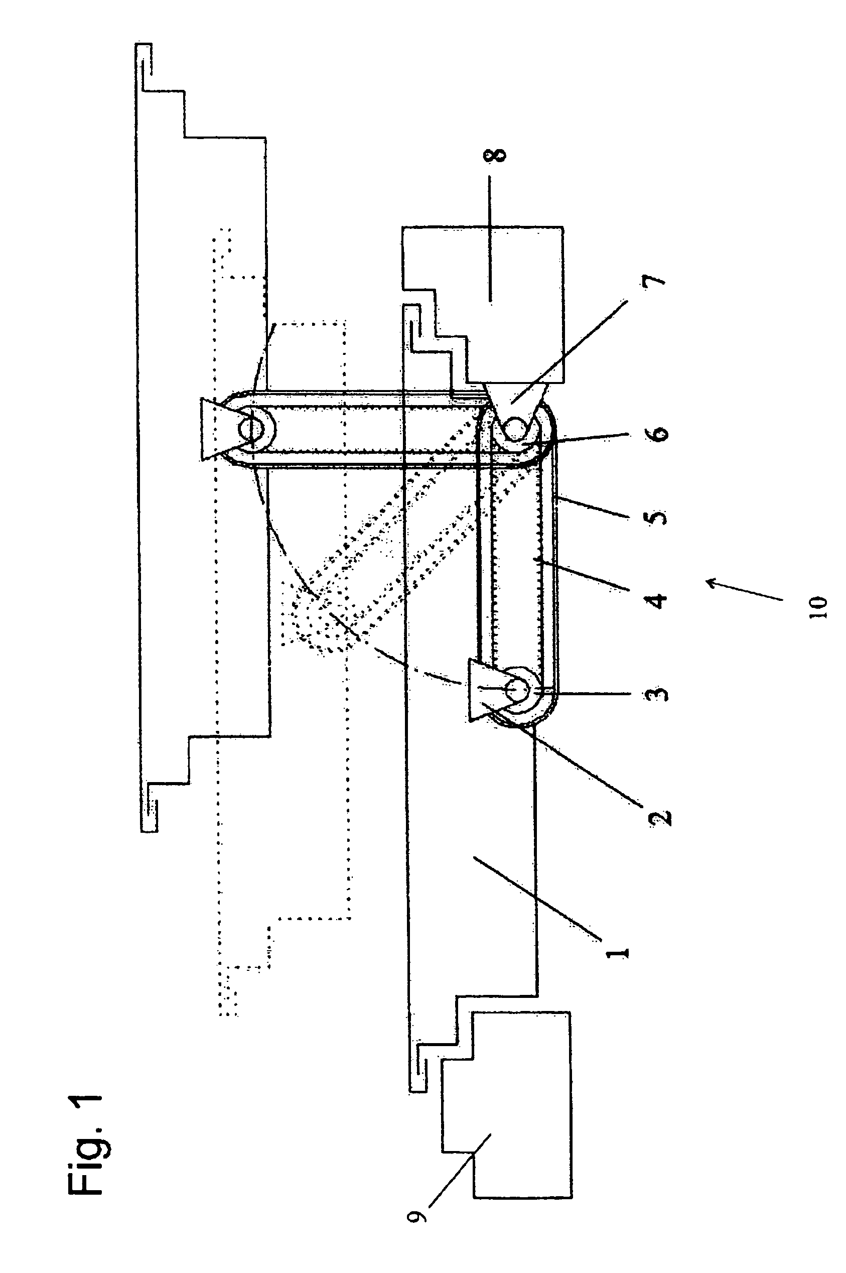
[0019]To clarify the principle of the invention and its effects, we shall first briefly explain the hinge device that is not in accordance with the invention as per FIG. 1. The figure shows a horizontal section through a door 1 of a motor vehicle and the posts 8, 9 of the body of a motor vehicle laterally surrounding the door 1. A hinge device generally designated by 10 comprises a first head piece 2 secured to the door 1 and a second head piece 7 secured to the right post 8 as well as an arm 5 to which the head pieces 2, 7 are joined to respectively pivot around an axis. The arm 5 is comprised by a hollow housing in the interior of which two belt pulleys 3, 6 are respectively connected in a twist-proof manner to the head pieces 2 or 7 through openings in the arm 5. An endless traction belt 4 is wrapped around the circumferential surfaces of the two belt pulleys 3, 6.

[0020]In the hinge device in FIG. 1, the belt pulleys 3, 6 are both circular and have the same diameter so that a rot...


PUM


Abstract

In the case of a hinge device with an arm and with two head pieces mounted to pivot / swivel on the ends of the arm around respectively one axis, the head pieces are respectively joined to revolve with one of the two belt pulleys, which are circumscribed by a common traction belt on one circumferential surface, and at least one of the belt pulleys is not circular but preferably elliptical.

Description

TECHNICAL FIELD[0001]The current invention concerns a hinge device, more specifically, but not necessarily, for the installation of a door on the body of a motor vehicle.BACKGROUND OF THE INVENTION[0002]So-called pantograph doors for buses have long been known. In them, a hinge device is formed by a pair of arms whose one end respectively attaches at the level of a body-mounted axis and whose other end attaches at the level of an axis connected to the door. The effective length of these two arms, that is to say, the spacing distance between their two axes, must be equal, and so must also the spacing distance between the two door side axes be equal, on the one hand, and the spacing distance between the two body-mounted axes on the other hand, so that the door maintains its orientation upon opening and closing and so that, in an open position, the door can hang next to the door opening and be parallel to said opening against the body.[0003]The parallel movement of the door leads to th...

Claims


Application Information

Patent Timeline
IPC IPC(8): E05D3/06E05D15/28
CPCE05D3/122E05D3/127E05D15/28E05Y2201/62Y10T16/5474E05Y2900/531Y10T16/541Y10T16/547E05Y2201/652
Inventor BORLEIS, DANIELHULBERT, JUERGENSCHENKENBERGER, JENSSTERN, ANDREAS
Owner GM GLOBAL TECH OPERATIONS LLC
Learn More