Apparatus for manufacturing taped insulated conductor and method of controlling tape winding tension

a technology of insulated conductors and manufacturing methods, which is applied in the direction of yarn, textiles and papermaking, thin material processing, etc., can solve the problems of large outside diameter, large porosity, and large dispersion of relative permittivity of insulator layers, so as to reduce the influence of winding winding force, reduce the effect of minimum tension and constant manufacturing speed

Active Publication Date: 2009-04-21
ADVANTEST CORP +1
View PDF12 Cites 30 Cited by
  • Summary
  • Abstract
  • Description
  • Claims
  • Application Information

AI Technical Summary

Benefits of technology

[0022]According to the present invention, the irregularities in the insulator outside diameter, and the dispersion of the outside diameter which are caused by the dispersion or the like of the winding tension can be reduced by fixing the tension and the winding angle of the porous tape body (especially having a porosity rate of 60% or more) to be wound around the wire material. In addition, the influence of the wind force due to the rotation is reduced in addition to the fixing of the winding tension of the porous tape body, which results in that the porous tape body can be prevented from being torn due to the winding and can be uniformly wound, and also the fluctuation, the undulation or the like of the insulator outside diameter can be prevented from occurring. The present application is based on Japanese patent application No. 2005-009638, the entire contents of which are incorporated herein by reference.
[0023]The present invention is constituted in the manner as described above, and thus offers the effects as will be described below. That is to say, according to the present invention, the tape body can be delivered from the tape pad while the tape delivering tension is held constant without relying on the number of windings of the tape body in accordance with the torque gradually decreasing control. Moreover, since the tension with which the tape body is wound around the wire material (conductor) is held constant in accordance with the control made by the tension control rolls provided in the tape winding flyer, it is easy to wind the tape body around the wire material, and thus the degree of adhesion of the tape body to the wire material in the winding is fixed. Consequently, it is possible to provide the apparatus for manufacturing a taped insulated conductor which is capable of manufacturing an electric wire through the stable tape winding.
[0024]In addition, each of the tape body delivery tension and the winding tension can be usually fixed without relying on the number of windings of the tape body in accordance with the torque gradually decreasing control, and can be made a minimum tension. Moreover, the influence of the wind pressure due to the winding can be reduced by making the tape body contact the tension control rolls and the tape guide rolls at intervals of a short period of time. Therefore, even the tape body having a small tension applied thereto can be wound around the wire material.
[0025]Furthermore, the tape winding flyer is driven synchronously with the drive motor of the receiving device in accordance with proportional control made by the tape winding flyer and the drive motor of the receiving device, which results in that the manufacturing speed and the product pitch can be made constant irrespective of an acceleration and a deceleration.

Problems solved by technology

In particular, in the coaxial cable which includes a fine-diameter conductor having an internal conductor size of 24 or more in AWG size, and which has a characteristic impedance value of 50Ω, the dispersions of the thickness, the outside diameter, the porosity, the firing process and the like of the insulator layer become a serious hindrance when the stabilization is realized by removing the dispersion of the transmission characteristics.
Therefore, irregularities in the outside diameter occur in a part in which the tape body is repeatedly wound around the outer periphery of the internal conductor due to the void parts and the repeated winding, so that the dispersions of the relative permittivity and the outside diameter become very large.
Also, the dispersions of the relative permittivity and the outside diameter further increase because a degree of adhesion between the internal conductor and the insulator after the winding work is very weak.
Moreover, there is encountered such a serious problem that it is difficult to form the insulator in right circle cylindrical shape as well as to keep the outside diameter of the insulator to a prescribed outside diameter, thereby removing the dispersion of the insulator outside diameter.
However, the conventional apparatus for manufacturing a taped insulated conductor involves the following problems.
(5) Since from the problems (1) and (2), the tape winding tension provided by the tape feed and the tape winding is not stabilized, and thus the tape winding becomes unstable, the external shape of the wound tape has irregularities, and also the tearing of the tape is easy to occur.
However, since the tape delivering tension is controlled (increased or decreased) in accordance with the specified torque, a large nonuniformity occurs in the tape delivering tension when the number of windings of the tape body changes.
(8) Although a receiving device for receiving the cable having the tape body wound therearound usually rotates at a set rotational frequency to receive the cable, no control is performed so that the cable receiving speed and the speed at which the tape body is wound around the cable are synchronized with each other, and thus the receiving device does not perform the receiving operation in which the winding-up pitch of the tape body is set as a specified value.

Method used

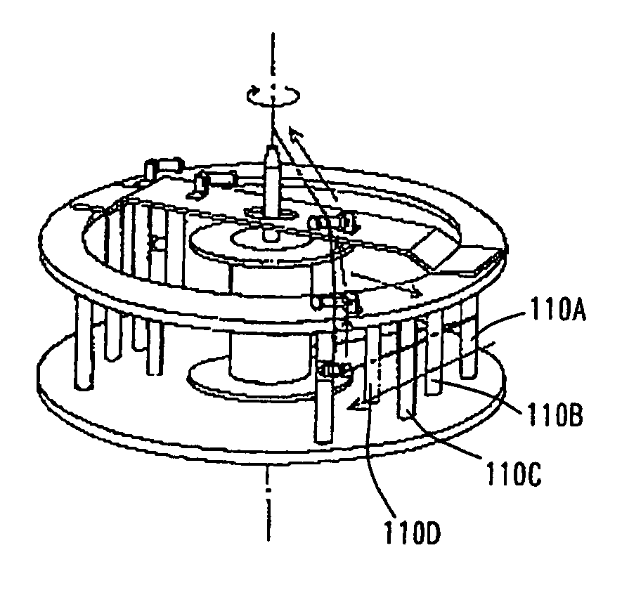
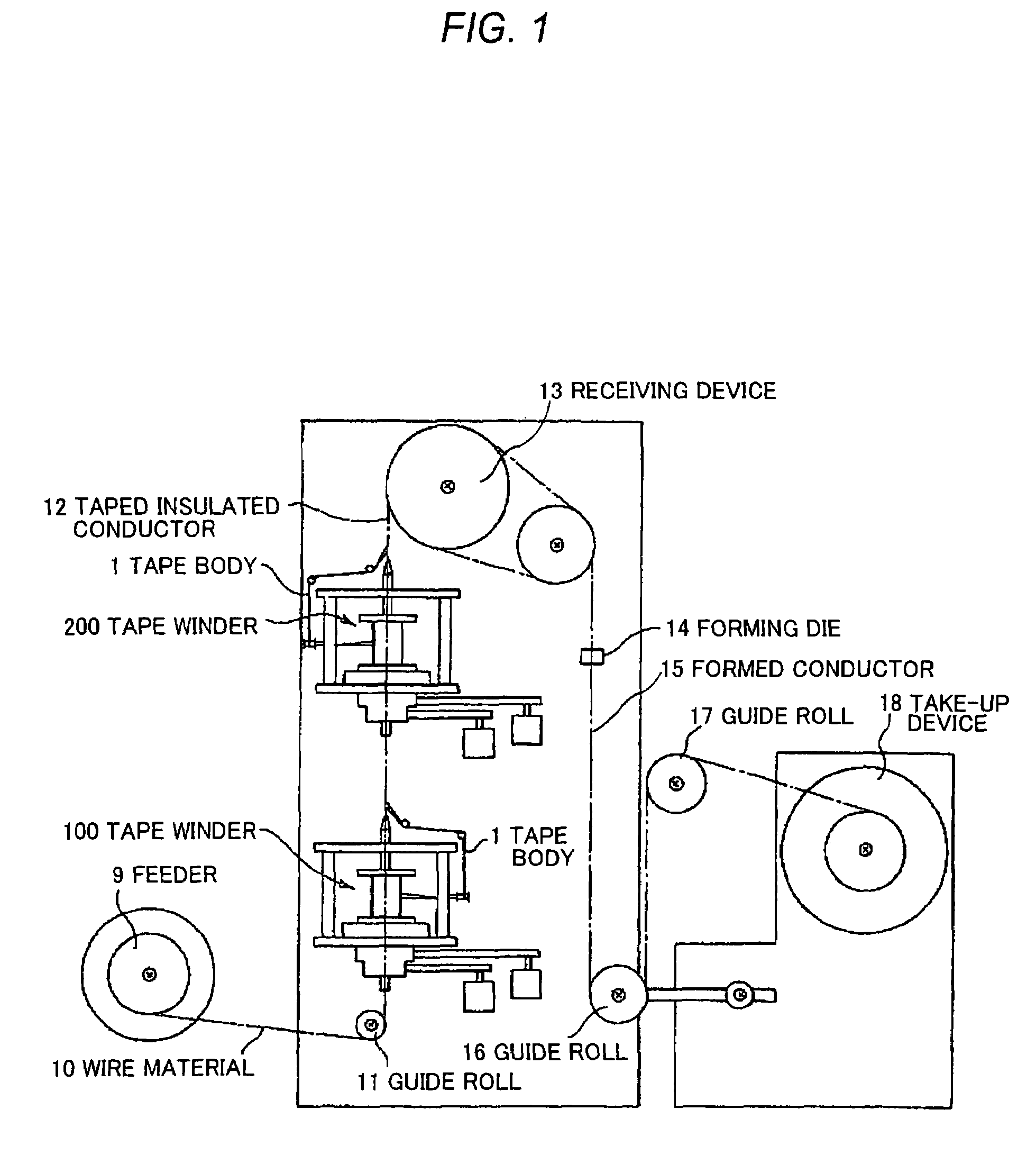
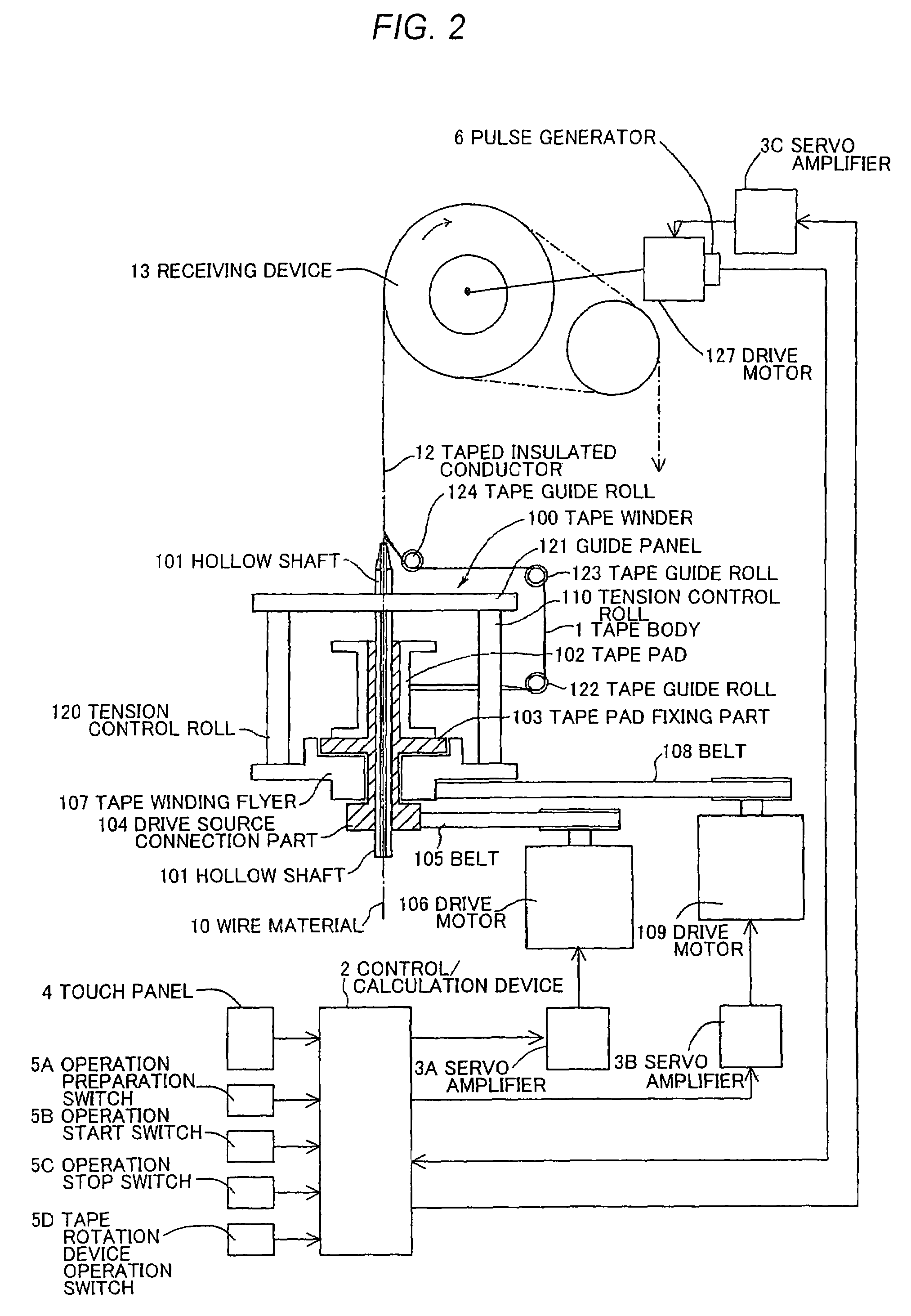

Image

  • Apparatus for manufacturing taped insulated conductor and method of controlling tape winding tension
  • Apparatus for manufacturing taped insulated conductor and method of controlling tape winding tension
  • Apparatus for manufacturing taped insulated conductor and method of controlling tape winding tension

Examples


example

[0069]FIG. 6 is a graph showing a relationship among the length (tape length) of the tape body 1, the output torque constant value, and the tape delivery tension. The output torque constant value of 100.00 and the data on the length of the tape body 1 of 900 m which correspond to the gradually decreasing value zero tension are inputted as the initial torque setting for the drive motor 106 by using the touch panel 4. In addition, the value of the number of rotations of 1500 rpm of the tape winding flyer 107 is inputted as the setting for the value of the number of rotations of the drive motor 109, and a value of 10000 m is inputted as a value of the length of the tape body received in the receiving device 13. In addition thereto, the product winding pitch set value of 6.6 mm is also inputted. In addition, a value of 200 m, and 60.00 are inputted as the value of the length of the tape body 1 used in the section in the first stage, and the end point torque value in the first stage of t...


PUM

PropertyMeasurementUnit
porosityaaaaaaaaaa
relative permittivityaaaaaaaaaa
impedanceaaaaaaaaaa

Abstract

An apparatus for manufacturing a taped insulated conductor and a method of controlling a tape winding tension. The apparatus comprises a wire material feeder feeding a wire material, a tape winder winding a tape body on the wire material fed from the wire material feeder, and a receiving device receiving the wire material on which the tape body is wound by the tape winder. A rotating shaft torque is controlled to a prescribed torque by rotatingly driving a tape pad fixing part by a torque gradually decreasing control without relying on the number of the windings of the tape body. Thus, the delivery tension of the tape body can be set to a specified prescribed value.

Description

FIELD OF THE INVENTION[0001]The present invention relates to an apparatus for manufacturing a taped insulated conductor and a method of controlling a tape winding tension, and more particularly to an apparatus for manufacturing a taped insulated conductor which forms an insulator on an outer periphery of a conductor by winding a very thin porous tape body around the outer periphery of the conductor, and a method of controlling a tape winding tension with which a winding work is stabilized by making a tape tension constant when a very thin porous tape is wound around an outer periphery of a conductor.DESCRIPTION OF THE RELATED ART[0002]A demand for high-speed promotion for a transmission speed, and an improvement in a transmission precision in information communication apparatuses, and semiconductor element testing / inspecting instruments or the like applied to the information communication apparatuses has increased with the progress of a recent advanced information-oriented society. ...

Claims


Application Information

Patent Timeline
Patent Type & Authority Patents(United States)
IPC IPC(8): D02G3/38
CPCH01B13/0866D07B7/14B65H81/02H01B13/00
Inventor SAITO, HISAONANJO, MITSUO
Owner ADVANTEST CORP
Why Eureka
Try Eureka