Hydraulic pressure control device of construction machine

a technology of hydraulic pressure control and construction machine, which is applied in the direction of fluid couplings, servomotors, couplings, etc., can solve the problems of wasteful pressure loss and energy loss, reduce work efficiency, and lose operability, so as to improve operability and work efficiency, the effect of improving operability

Active Publication Date: 2009-04-21
KOMATSU LTD
View PDF16 Cites 24 Cited by
  • Summary
  • Abstract
  • Description
  • Claims
  • Application Information

AI Technical Summary

Benefits of technology

[0024]However, when turning the pressure compensation ON and OFF at the same time as connecting with or blocking the first and the second discharge fluid passages in this way, fluctuations in the flow rates of the fluids that pass through the first and the second discharge fluid passages are produced before and after switching the merging / separating valve, operability is lost, and work efficiency decreases.
[0123]The present ninth invention thereby improves energy efficiency and work efficiency when performing complex operations of a plurality of work devices (a plurality of hydraulic actuators 4, 7) by correctly determining the time for switching the first and the second merging / separating valves 13, 21 to the merge position and by controlling energy loss due to pressure loss of the pressure compensation valves 6, 9 because the decision to switch to the merge position is made when calculating the necessary flow rates Q1d, Q2d of the first and the second hydraulic actuators 4, 7 and determining that at least one of the necessary flow rates Q1d, Q2d is the maximum discharge flow rate Qmax or more per pump of the first and the second hydraulic pumps 2, 3.

Problems solved by technology

However, when turning the pressure compensation ON and OFF at the same time as connecting with or blocking the first and the second discharge fluid passages in this way, fluctuations in the flow rates of the fluids that pass through the first and the second discharge fluid passages are produced before and after switching the merging / separating valve, operability is lost, and work efficiency decreases.
For this reason, using the pressure compensation valve (first pressure compensation valve) of the small load side produces useless pressure loss and energy loss.

Method used


Image

  • Hydraulic pressure control device of construction machine
  • Hydraulic pressure control device of construction machine
  • Hydraulic pressure control device of construction machine

Examples


Embodiment Construction

[0132]Embodiments of a hydraulic pressure control device of a construction machine according to the present invention will be described with reference to the accompanying drawings.

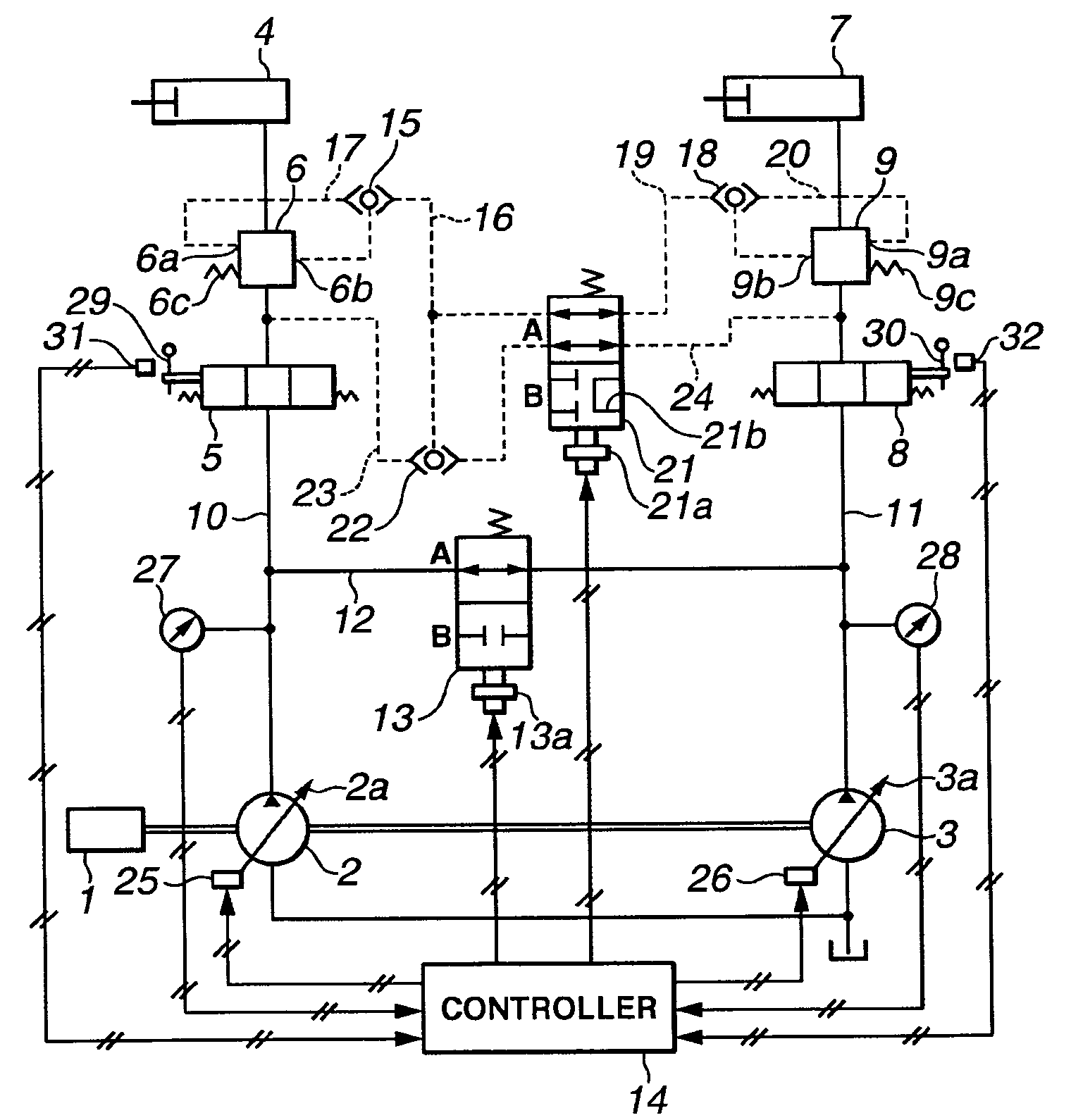
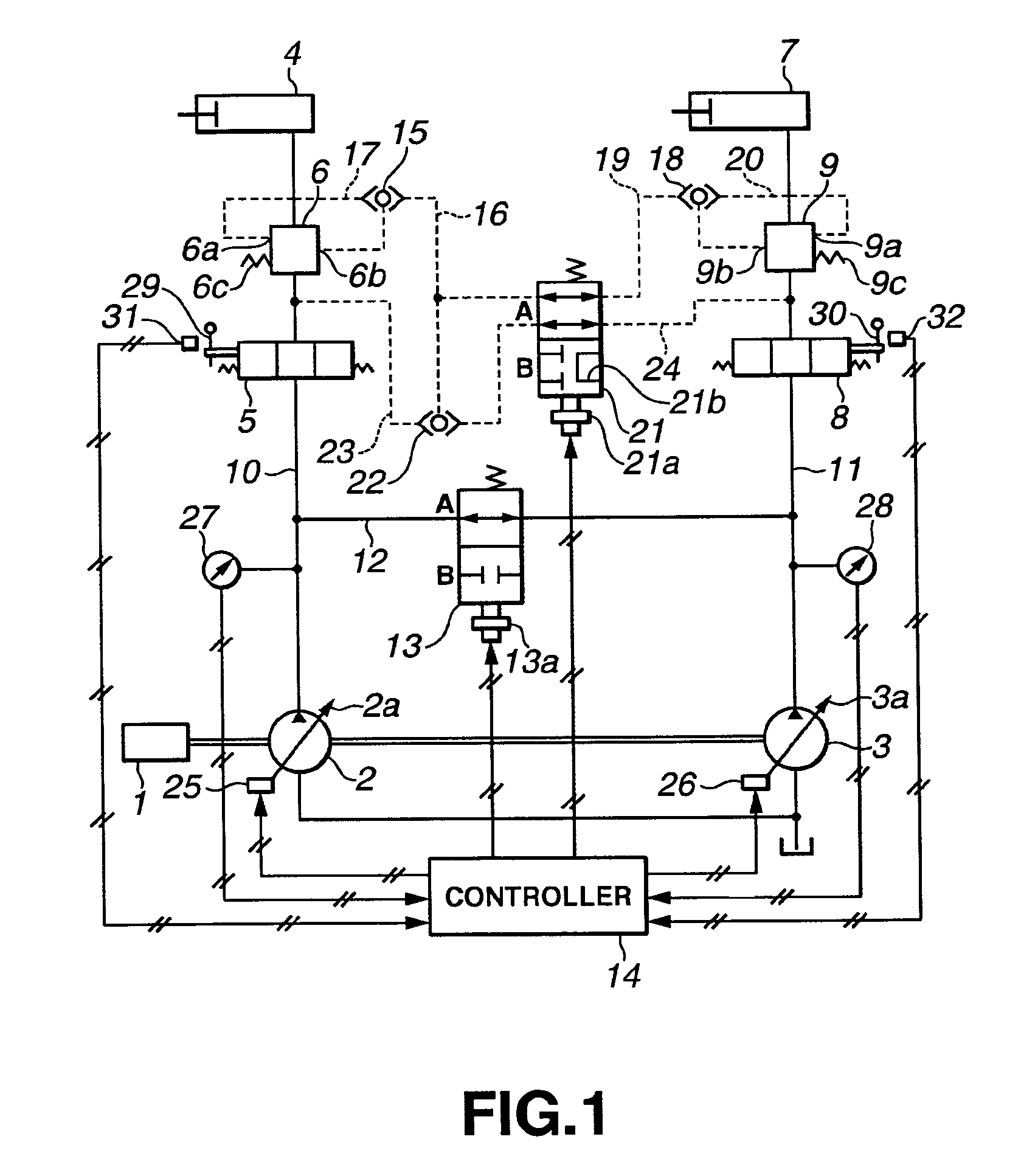
[0133]FIG. 1 is a hydraulic circuit diagram indicating an embodiment of the hydraulic pressure control device of a construction machine related to the present invention. FIG. 1 indicates a hydraulic circuit mounted in a hydraulic pressure shovel.

[0134]The shovel is provided with a plurality of work devices such as a boom, an arm and a bucket, etc. and an upper rotating body, and these plurality of work devices and the upper rotating body are respectively operated by corresponding first hydraulic actuator 4 for a work device and second hydraulic actuator 7 for a work device. The first hydraulic actuator 4 and the second hydraulic actuator 7 are configured by a hydraulic pressure cylinder or a hydraulic pressure motor, but for the sake of an explanation, are indicated by hydraulic pressure cylinders in FIG. ...


PUM


Abstract

A hydraulic pressure control device of a construction machine enabling an increase in operability and working efficiency by suppressing a fluctuation in flow rates occurring before and after the switching of a merging-separating valve, in energy efficiency by accurately determining the switching timing of the merging-separating valve to suppress the pressure energy loss of a pressure compensating valve, and working efficiency in the compound motion of plural hydraulic actuators. When a controller determines that necessary flow rates of first and second hydraulic actuators are less than maximum discharge flow rate of each of first and second variable displacement hydraulic pumps when the first merging-separating valve is in a merging position, the switching of the first merging-separating valve is controlled so that firstly the first merging-separating valve is switched to a separating position and, after the switching is completed, the second merging-separating valve is switched.

Description

TECHNICAL FIELD[0001]The present invention relates to a hydraulic pressure control device of a construction machine, and more particularly relates to a hydraulic pressure control device that switches a plurality of fluid discharge passages to the merge state or separation state in a hydraulic circuit in which pressure oil discharged from a plurality of hydraulic pumps is supplied to a plurality of hydraulic actuators via the plurality of fluid discharge passages and a plurality of main operation valves.BACKGROUND ART[0002]In a construction machine such as hydraulic pressure shovels, etc., a plurality of work devices and upper revolving bodies such as booms, arms, and buckets are provided, and these plurality of work devices and upper revolving bodies are variously driven and operated by corresponding a plurality of hydraulic actuators (hydraulic pressure cylinders, hydraulic pressure motors).[0003]Normally, a plurality of (2 units) variable displacement hydraulic pumps, specifically...

Claims


Application Information

Patent Timeline
Patent Type & Authority Patents(United States)
IPC IPC(8): F16D31/02F15B11/17
CPCF15B11/17F15B2211/20546F15B2211/20576F15B2211/3054F15B2211/40515F15B2211/41518F15B2211/426F15B2211/6054F15B2211/6309F15B2211/6336F15B2211/65F15B2211/6652F15B2211/7142E02F9/2235E02F9/2242F15B11/163F15B11/165E02F9/20E02F9/22
Inventor TANAKA, JUNSEIHATAKE, KAZUHIRO
Owner KOMATSU LTD
Why Eureka
Try Eureka