Methods and apparatus for injecting fluids into a turbine engine

a technology of turbine engines and fluid injection, which is applied in the ignition of turbine/propulsion engines, combustion types, lighting and heating apparatus, etc., can solve the problems of co emissions, higher co emissions, and generally insufficient carbon monoxide (co) emission requirements of engines, and achieve the effect of facilitating primary fuel mixing

Active Publication Date: 2009-04-21
GENERAL ELECTRIC CO
View PDF17 Cites 91 Cited by
  • Summary
  • Abstract
  • Description
  • Claims
  • Application Information

AI Technical Summary

Benefits of technology

[0004]In one aspect, a method of operating a gas turbine engine is provided. The method includes discharging pilot fuel into a combustion chamber from a nozzle through at least one pilot fuel outlet defined in a tip of the nozzle, discharging steam from the nozzle through a plurality of steam outlets that are spaced circumferentially about the plurality of pilot fuel outlets, and discharging primary fuel from the nozzle through a plurality of primary fuel outlets that are circumferentially aligned with the plurality of steam outlets. To facilitate mixing the primary fuel with the steam, the primary fuel is discharged from the nozzle tip at an oblique angle with respect to a centerline extending through the nozzle tip.
[0005]In another aspect, a nozzle tip for a turbine engine fuel nozzle is provided. The nozzle tip includes an annular body having a centerline extending there through. The annular body includes at least one pilot fuel outlet configured to discharge only pilot fuel from the nozzle tip, and a plurality of steam outlets configured to discharge steam from the nozzle tip. The plurality of steam outlets are spaced circumferentially about the at least one pilot fuel outlet. The annular body also includes a plurality of primary fuel outlets configured to discharge primary fuel from the nozzle tip. The plurality of primary fuel outlets are circumferentially aligned with the plurality of steam outlets. The plurality of primary fuel outlets are configured to discharge primary fuel at an oblique angle with respect to the centerline to facilitate mixing the primary fuel with the steam.
[0006]In a further aspect, a gas turbine engine is provided. The gas turbine engine includes a combustor and a fuel nozzle for injecting fluids into the combustor. The nozzle includes a nozzle tip comprising an annular body having a centerline. The nozzle tip is in flow communication with the combustor. The nozzle tip also includes at least one pilot fuel outlet configured to discharge only pilot fuel from the nozzle tip, and a plurality of steam outlets configured to discharge steam from the nozzle tip. The plurality of steam outlets are spaced circumferentially about the at least one pilot fuel outlet. The nozzle tip also includes a plurality of primary fuel outlets configured to discharge primary fuel from the nozzle tip. The plurality of primary fuel outlets are circumferentially aligned with the plurality of steam outlets. The plurality of primary fuel outlets are configured to discharge primary fuel at an oblique angle with respect to the centerline to facilitate mixing the primary fuel with the steam.

Problems solved by technology

Moreover, the generally high capital costs associated with the purchase and maintenance of turbine engines, such as revenue losses generated during engine outages, have caused the same engine manufacturers to attempt to design engines that are more reliable and that have extended useful life.
At least some known gas turbine engines operating with gas and steam do not meet emissions requirements at all operating conditions, and in particular, such engines generally do not satisfy carbon monoxide (CO) emission requirements as well as other known engines.
More specifically, poor mixing of the gas and steam may cause fuel to remain towards a centerline of the nozzle, leading to higher CO emissions being generated.
Moreover, the axial, non-swirled injection of the gas and steam may cause the recirculation stability zone within the combustor to be shifted downstream, which may cause the flame to become detached, resulting in the generation of CO emissions.

Method used


Image

  • Methods and apparatus for injecting fluids into a turbine engine
  • Methods and apparatus for injecting fluids into a turbine engine
  • Methods and apparatus for injecting fluids into a turbine engine

Examples


Embodiment Construction

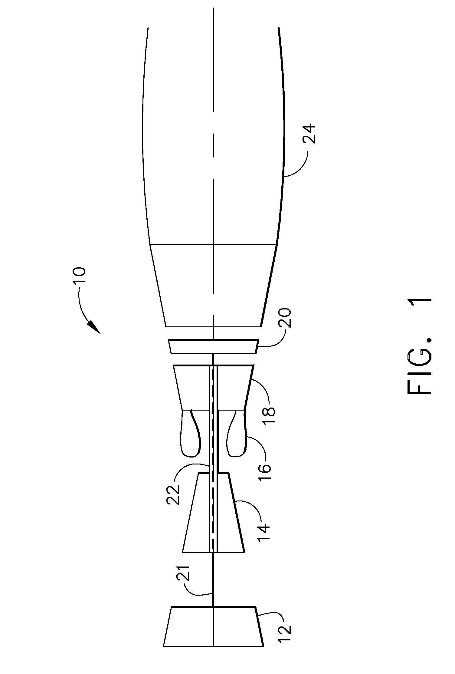
[0012]FIG. 1 is a schematic illustration of an exemplary gas turbine engine 10. Engine 10 includes a low pressure compressor 12, a high pressure compressor 14, and a combustor assembly 16. Engine 10 also includes a high pressure turbine 18, and a low pressure turbine 20 arranged in a serial, axial flow relationship. Compressor 12 and turbine 20 are coupled by a first shaft 21, and compressor 14 and turbine 18 are coupled by a second shaft 22.

[0013]In operation, air flows through low pressure compressor 12 supplying compressed air from low pressure compressor 12 to high pressure compressor 14. The highly compressed air is delivered to combustor 16. Airflow from combustor 16 is channeled through a turbine nozzle to drive turbines 18 and 20, prior to exiting gas turbine engine 10 through an exhaust nozzle 24. As is known in the art, gas turbine engines further include fuel nozzles (not shown) which supply fuel to the combustor 16.

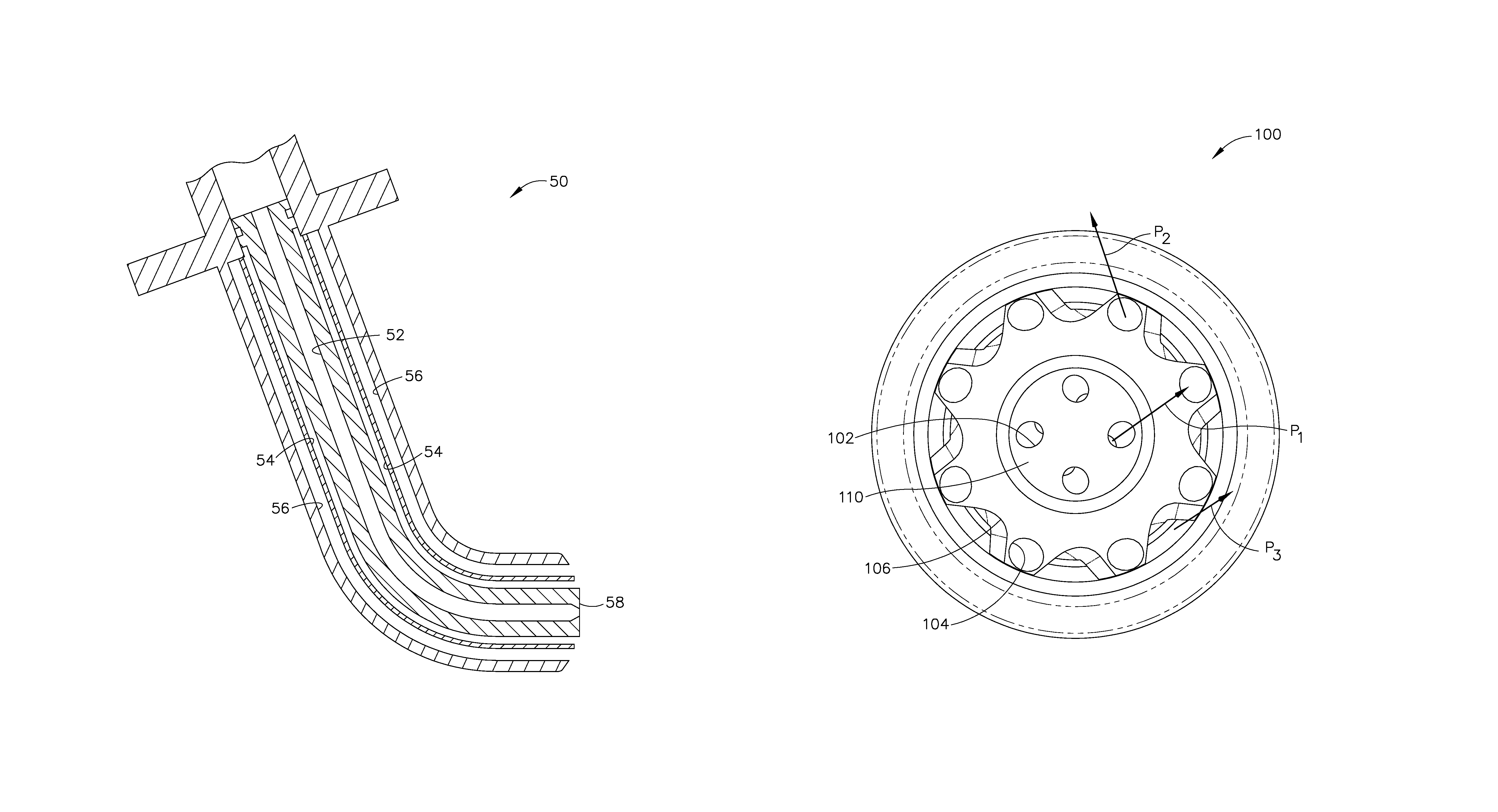
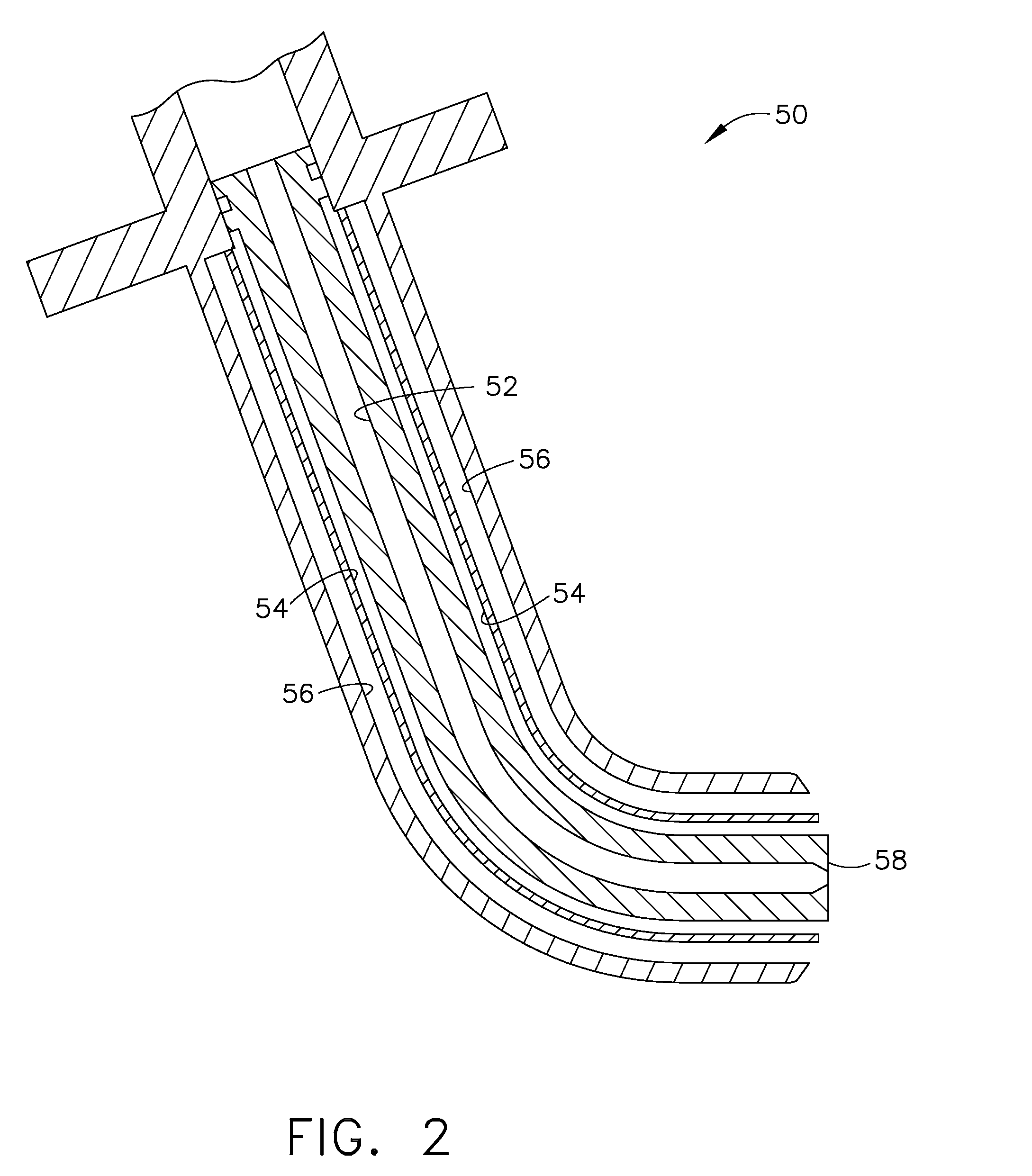
[0014]FIG. 2 is a side schematic cross-sectional view of...


PUM


Abstract

A method of operating a gas turbine engine is provided. The method includes discharging pilot fuel into a combustion chamber from a nozzle through at least one pilot fuel outlet defined in a tip of the nozzle, discharging steam from the nozzle through a plurality of steam outlets that are spaced circumferentially about the plurality of pilot fuel outlets, and discharging primary fuel from the nozzle through a plurality of primary fuel outlets that are circumferentially aligned with the plurality of steam outlets. To facilitate mixing the primary fuel with the steam, the primary fuel is discharged from the nozzle tip at an oblique angle with respect to a centerline extending through the nozzle tip.

Description

BACKGROUND OF THE INVENTION[0001]This application relates generally to gas turbine engines and, more particularly, to methods and apparatus for injecting fluids into turbine engines.[0002]Air pollution concerns worldwide have led to stricter emissions standards both domestically and internationally. These same standards have caused turbine engine manufacturers to design more efficient engines, as well as design improved retrofit components that enable engines to operate more efficiently, with improved emissions, and / or with extended useful life and reliability. Moreover, the generally high capital costs associated with the purchase and maintenance of turbine engines, such as revenue losses generated during engine outages, have caused the same engine manufacturers to attempt to design engines that are more reliable and that have extended useful life.[0003]Controlling the mixture of fluids, i.e. gas and steam, delivered to a gas turbine engine may be critical to the engine's performan...

Claims


Application Information

Patent Timeline
Patent Type & Authority Patents(United States)
IPC IPC(8): F02C1/00
CPCF02C3/30F23D11/383F23D14/48F23L7/005F23R3/343F05B2250/31F05B2250/314F23D14/58
Inventor DURBIN, MARK D.DANIS, ALLEN MICHAELHELD, TIMOTHY JAMESDURSTOCK, DANIELCOOPER, JAMES N.FORTUNA, DOUGLAS MARTI
Owner GENERAL ELECTRIC CO
Why Eureka
Try Eureka