Drive unit for controlling reciprocating electromagnets

a technology of reciprocating electromagnets and drive units, which is applied in the direction of motors/generators/converter stoppers, auxillary welding devices, mechanical control devices, etc., can solve the problems of increasing mechanical stresses on the welder, reducing process efficiency, and competition between the electromagnets

Active Publication Date: 2009-04-21
ROCKWELL AUTOMATION TECH
View PDF4 Cites 15 Cited by
  • Summary
  • Abstract
  • Description
  • Claims
  • Application Information

AI Technical Summary

Benefits of technology

[0010]The present inventors have recognized that a three-phase drive unit may be configured to control the drive signals applied to the reciprocating electromagnets of a vibration welder to ensure that the drive signals are precisely 180 degrees out of phase to thereby eliminating competition between the electromagnets.

Problems solved by technology

This fighting between the electromagnets, repeated every cycle, increases mechanical stresses on the welder, and reduces the efficiency of the process.
Competition between the electromagnets reduces the effectiveness at which these variable may be controlled.
This approach creates a resonance condition, and the drive signals are not completely synchronized, such that competition exists between the electromagnets.

Method used


Image

  • Drive unit for controlling reciprocating electromagnets
  • Drive unit for controlling reciprocating electromagnets
  • Drive unit for controlling reciprocating electromagnets

Examples


Embodiment Construction

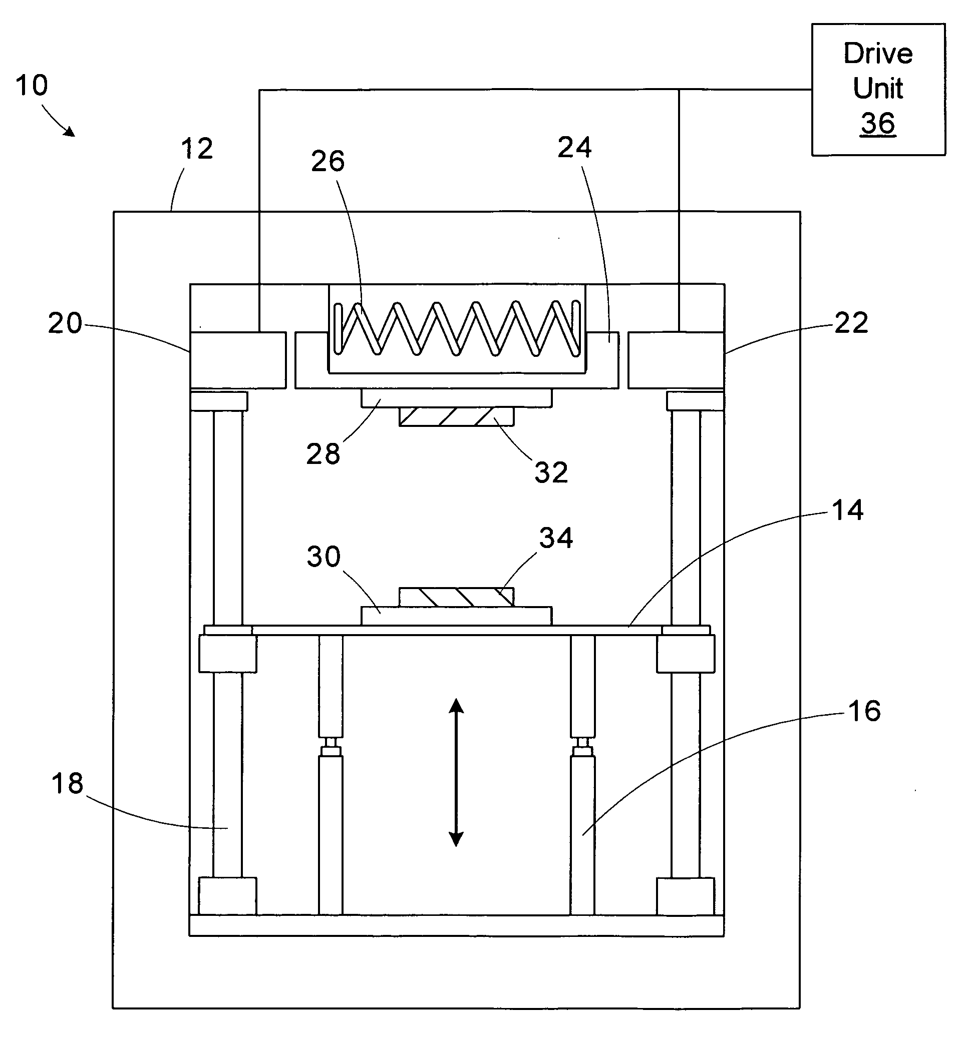
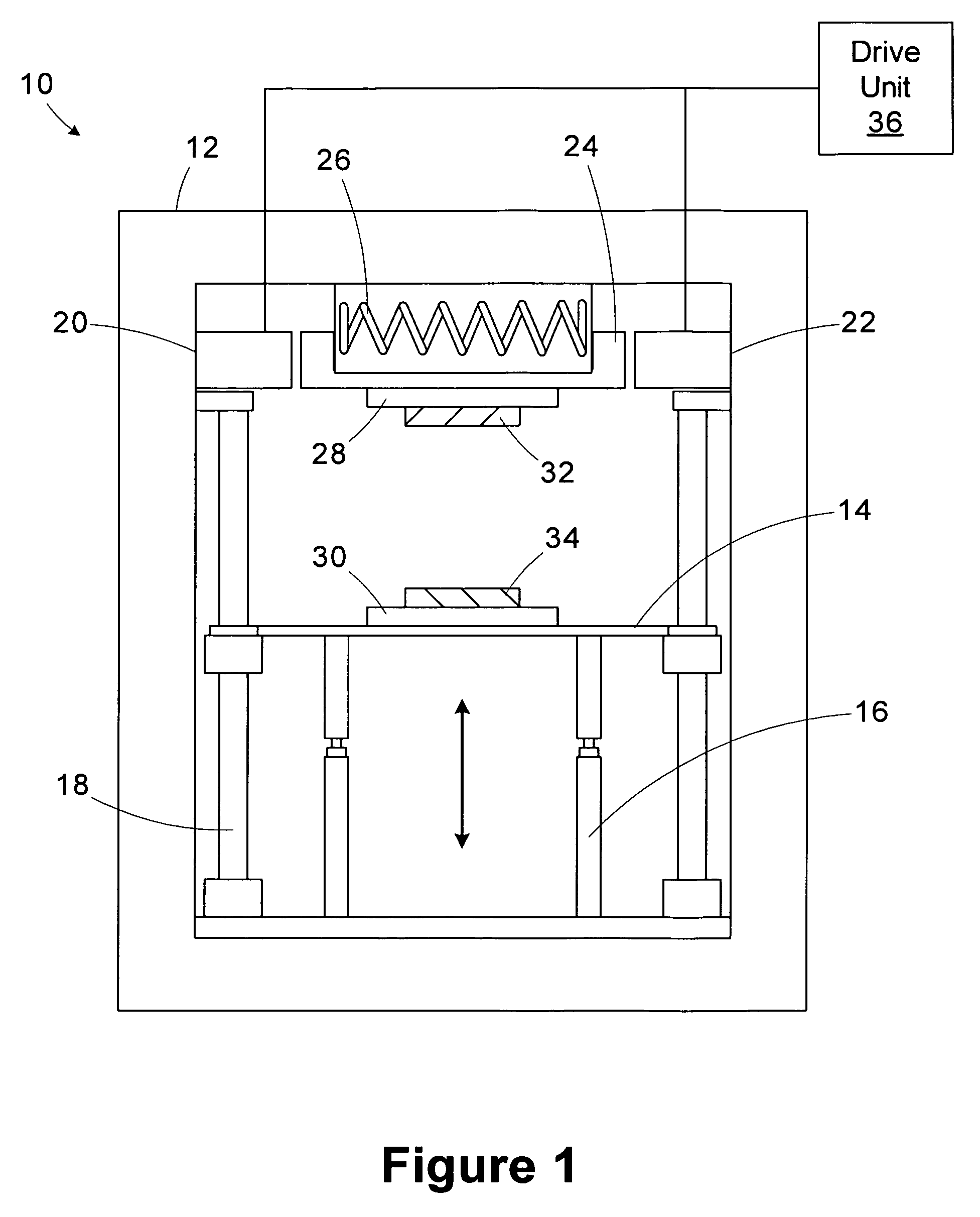
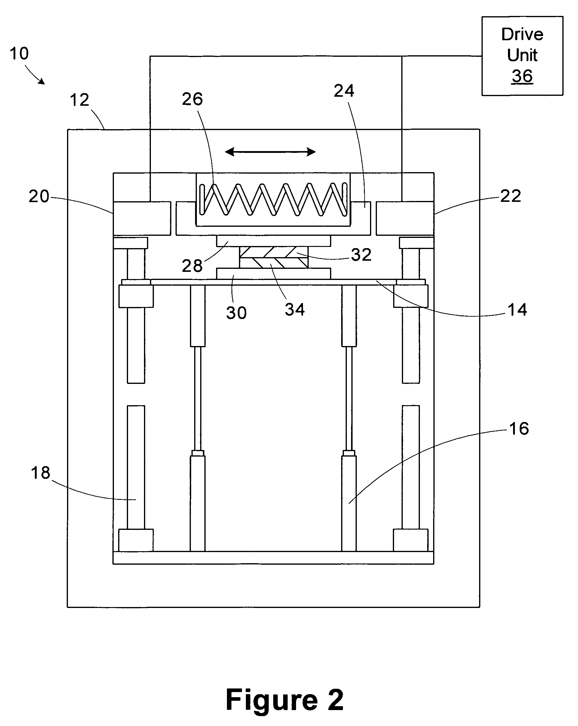
[0022]One or more specific embodiments of the present invention will be described below. It is specifically intended that the present invention not be limited to the embodiments and illustrations contained herein, but include modified forms of those embodiments including portions of the embodiments and combinations of elements of different embodiments as come within the scope of the following claims. It should be appreciated that in the development of any such actual implementation, as in any engineering or design project, numerous implementation-specific decisions must be made to achieve the developers' specific goals, such as compliance with system-related and business related constraints, which may vary from one implementation to another. Moreover, it should be appreciated that such a development effort might be complex and time consuming, but would nevertheless be a routine undertaking of design, fabrication, and manufacture for those of ordinary skill having the benefit of this...


PUM

PropertyMeasurementUnit
phaseaaaaaaaaaa
pulse widthaaaaaaaaaa
voltageaaaaaaaaaa

Abstract

A drive unit for use with a vibration welder having first and second electromagnets, each having first and second terminals, and being operable to reciprocate a vibration platen, includes phase U, V, and W drive circuitry and control circuitry. The phase U drive circuitry is coupled to the first terminal of the first electromagnet. The phase V drive circuitry is coupled to the first terminal of the second electromagnet. The phase W drive circuitry is coupled to the second terminals of the first and second electromagnets. The control circuitry is operable to control the phase U, V, and W drive circuitry to generate a first drive signal for energizing the first electromagnet and a second drive signal for energizing the second electromagnet.

Description

CROSS-REFERENCE TO RELATED APPLICATIONS[0001]Not applicable.STATEMENT REGARDING FEDERALLY SPONSORED RESEARCH OR DEVELOPMENT[0002]Not applicableBACKGROUND OF THE INVENTION[0003]The present invention relates generally to industrial control and, more particularly, to a drive unit for controlling reciprocating electromagnets.[0004]Vibration welding is an industrial process for creating a weld joint coupling two items, typically formed of thermoplastic material. In a linear vibration welding process, one of two parts is moved to slide across the other in a reciprocating fashion under pressure, creating heat through surface friction that melts and welds the parts together at the interface of the parts. As the melted material cools, a molecular bond is formed between the joined surfaces completing the weld.[0005]Linear vibration welders are designed with electromagnetic heads to reduce wear and the need for lubrication associated with bearing surfaces. To control the motion of the reciproc...

Claims


Application Information

Patent Timeline
Patent Type & Authority Patents(United States)
IPC IPC(8): B32B37/00
CPCH02P25/027B23K20/106B29C66/9512B29C66/1122B29C66/45B29C65/0618B29C66/7392B29C66/8242B29C66/8322B29C65/06B29C66/71H02P25/032
Inventor SIEGLER, DAVID W.GILMORE, THOMAS P.STRAW, WILLIAM D.
Owner ROCKWELL AUTOMATION TECH
Why Eureka
Try Eureka