Multicolor Photolithography Materials and Methods

a technology of photolithography and materials, applied in the field of photoresist compositions, can solve the problems of increasing difficulty in optics and material chemistry, and increasing difficulty in generating, propagating and manipulating light, etc., to achieve the effect of eliminating competition, generating, propagating and manipulating easily

Active Publication Date: 2017-06-15
UNIV OF MARYLAND
View PDF0 Cites 2 Cited by
  • Summary
  • Abstract
  • Description
  • Claims
  • Application Information

AI Technical Summary

Benefits of technology

[0020]The three-color approach eliminates the competition between deactivation and initiation, and additionally allows all three colors of light to be patterned to attain substantially superior resolution as compared to prior approaches. In the disclosed three-color photolithography approach, deactivation occurs from a pre-activated state. Only after the desired regions have been deactivated are the remaining PI molecules transferred to the activated state from which chemistry occurs, thus eliminating the competition between these processes.
[0021]The disclosed methods provide many advantages over prior lithography approaches. It should be understood that light as used herein refers to electromagnetic radiation within the electromagnetic spectrum, e.g., including ultraviolet light (preferably having wavelengths from about 100 nm to about 400 nm), visible light (with wavelengths from about 400 nm to about 700 nm), and infrared light (with wavelengths from about 700 nm to about 1 mm). In some embodiments, visible light may be utilized, which can be generated, propagated, and manipulated readily and at relatively low cost. Moreover, the disclosed methods are much gentler on a wide range of materials as compared to short-wavelength radiation, offering many more options to photoresist chemistry. In disclosed embodiments, efficient photoresist chemistry is provided that may be implemented in thin films for large-area, linear exposure, which are compatible with high-fidelity pattern transfer.

Problems solved by technology

This relationship has created great challenges for the continued progress of Moore's Law, as conventional photolithographic approaches are not focusing on the use of extreme ultraviolet (EUV) light, given EUV is expensive and difficult to generate, propagate and manipulate.
However, each reduction in wavelength brings its own set of challenges in optics and material chemistry.
As the wavelength of light becomes shorter, generating, propagating, and manipulating the light becomes increasingly difficult and expensive.
Moreover, the light tends to interact with virtually every material, requiring that propagation occur in a vacuum and that special, relatively expensive optics be used for manipulation.
As such, it becomes more challenging to develop suitably robust resist materials.
Ideally, the aerial image forms a square-wave intensity profile, but at extreme resolution the image quality is lost because the NA filters out higher diffraction orders.
The loss of the electric field information contained in these higher diffraction orders results in a degraded image.
Such overexposure results in the loss of the image to be printed and / or feature resolution.
In such two-color approaches, the range of materials that undergo these processes without undesirable side reactions has been very limited.
This competition invariably leads to the buildup of background exposure when tightly-packed features are created, ultimately limiting the resolution that can be attained using such approaches.
Thus, a limitation of such conventional two-color approaches is that, although features can be much smaller than either of the wavelengths of light employed, the minimum pitch (i.e., the distance between two features) is determined by the wavelength used for deactivation.
However, in such two-color approaches, deactivation and chemistry both occur from the same state, and so these processes necessarily compete with one another.
As a result, it is not possible to completely deactivate a region of the photoresist that has been excited.
This phenomenon leads to a degradation of the resolution as the number of patterning steps increases.

Method used


Image

  • Multicolor Photolithography Materials and Methods
  • Multicolor Photolithography Materials and Methods
  • Multicolor Photolithography Materials and Methods

Examples


Embodiment Construction

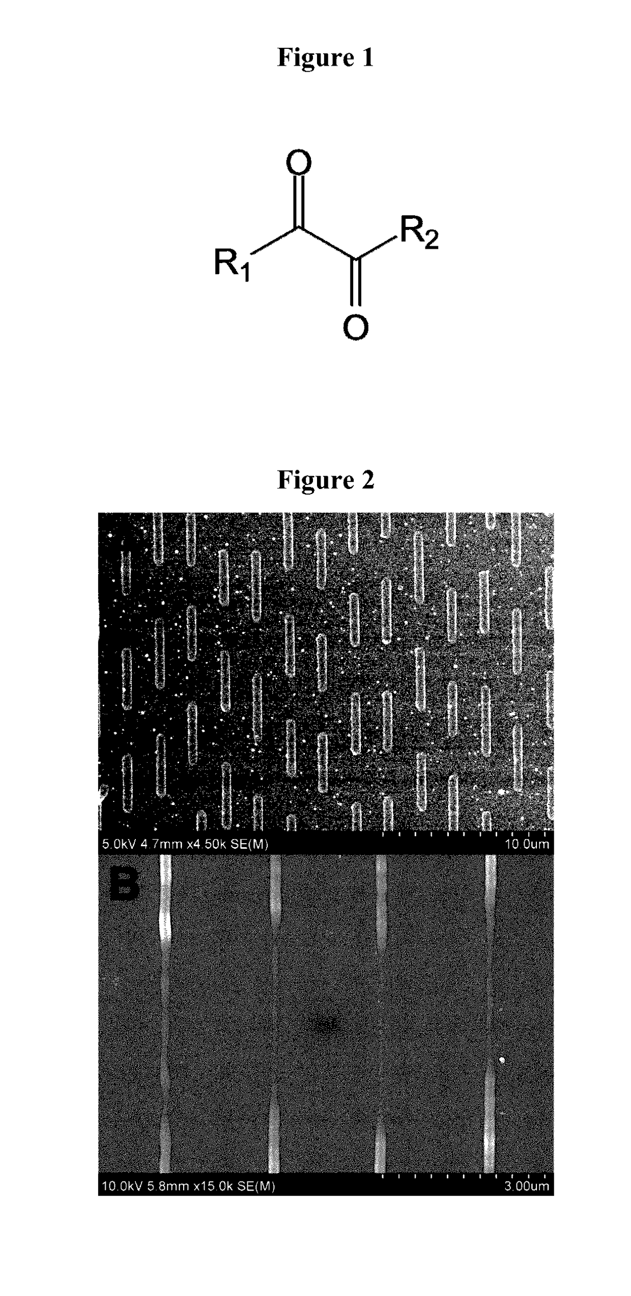
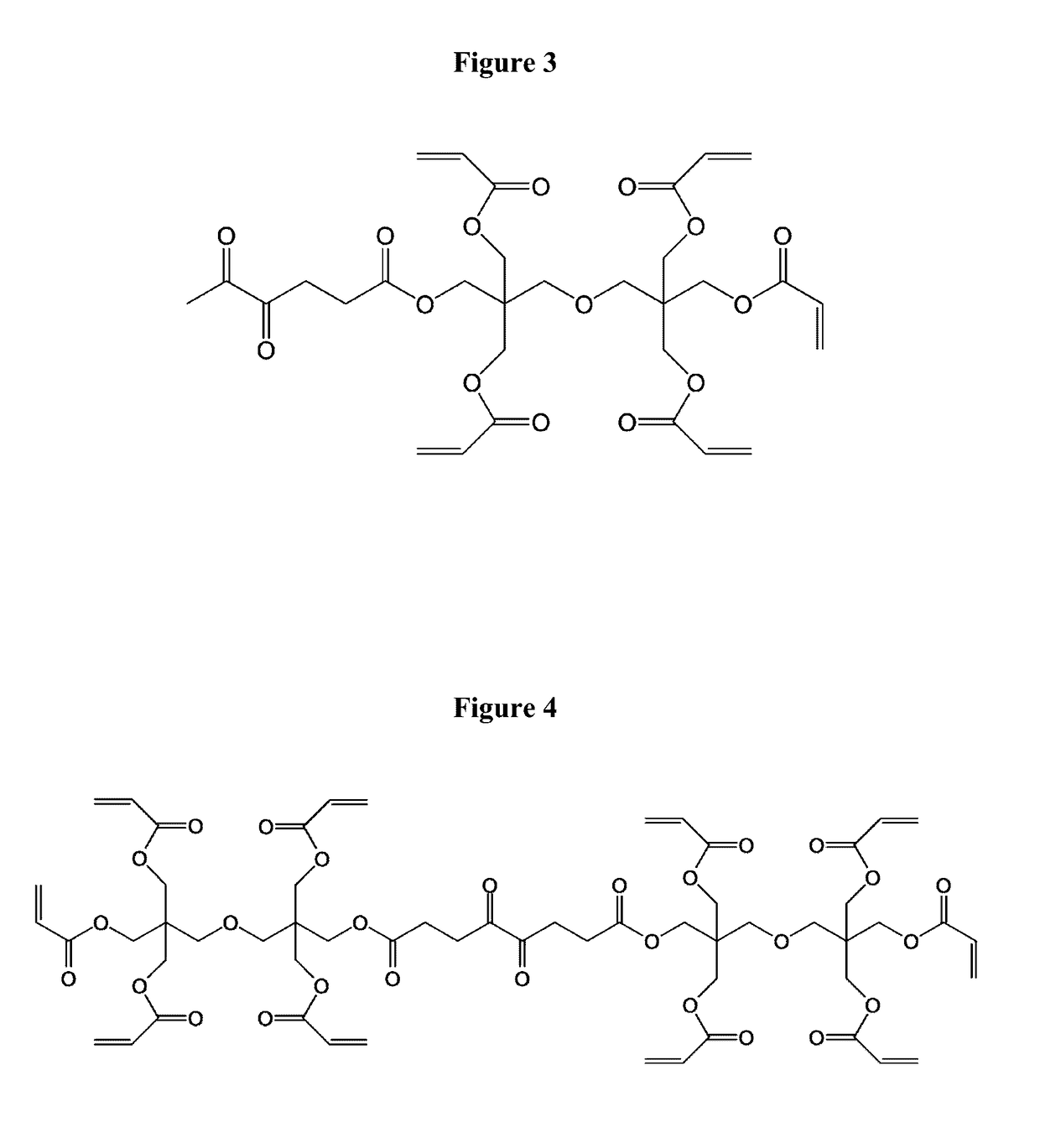
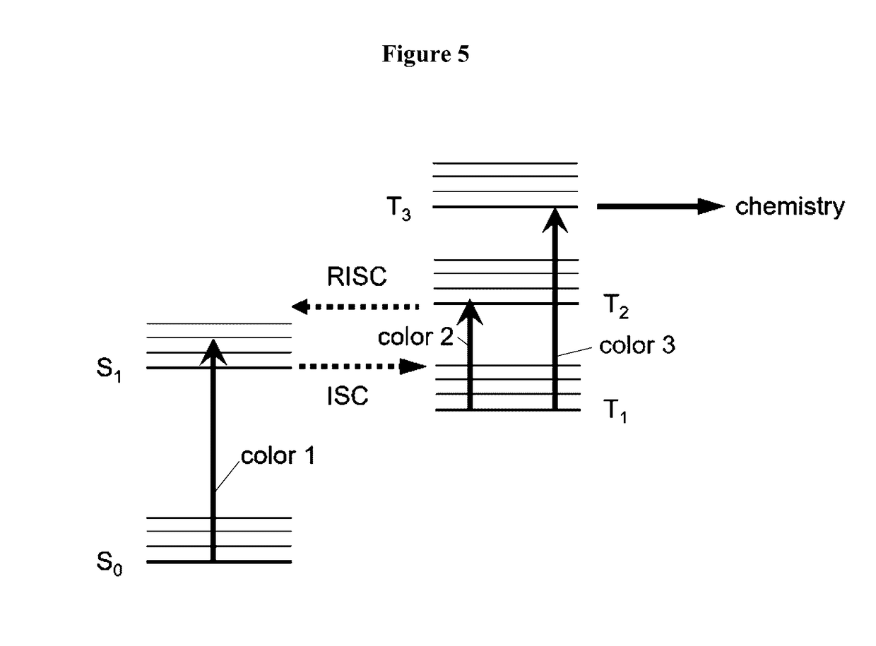
[0040]The present invention is directed to photoresist compositions and photolithography methods preferably utilizing the disclosed compositions. The photoresist compositions comprise a class of molecules that act as three-color radical photoinitiators. The operating principle of the disclosed materials is to use a first radiation source that emits a first color or wavelength of light to excite the molecules to an unreactive, “pre-activated” state. A second radiation source emits a second color or wavelength of light which deactivates the molecules in selected spatial locations. Finally, a third radiation source emits a third color or wavelength of light takes any remaining pre-activated molecules to an activated state that leads to chemical reaction. Note that the first, second and third colors or wavelengths of light may be different and / or alternatively have differing emission characteristics (e.g., such as pulsed, continuous wave, etc.). Thus, in some embodiments, the first, sec...


PUM

PropertyMeasurementUnit
weight percentaaaaaaaaaa

Abstract

The present invention relates to photoresist compositions comprising a base resin such as a monomer capable of radical polymerization upon photoinitiation, and photoinitiator molecules such as a diketone, and multicolor photolithography methods. Photoresist compositions comprise photoinitiator molecules that are exposed to a first radiation source, thereby exciting the photoinitiator molecules from a ground state to a pre-activated state. The pre-activated state molecules are then exposed to a second radiation source in selected locations, thereby deactivating the pre-activated state molecules in the selected locations. Any remaining pre-activated state molecules are exposed to a third radiation source, exciting such remaining pre-activated state photoinitiator molecules to an activated state. Polymerization of the base resin is then initiated.

Description

CROSS-REFERENCE TO RELATED APPLICATIONS[0001]This application is based on U.S. Provisional Patent Application Ser. No. 62 / 267,127, entitled “Materials for Multicolor Photolithography,” filed Dec. 14, 2015, which application is incorporated herein by reference in its entirety and to which priority is claimed.STATEMENT REGARDING FEDERALLY SPONSORED RESEARCH OR DEVELOPMENT[0002]This invention was made with government support by the National Science Foundation (NSF) under CMMI1449309 and IIP1318211. The United States government has certain rights in this invention.FIELD OF THE INVENTION[0003]The present invention relates to photoresist compositions comprising a base resin and diketone photoinitiator molecules, and methods preferably utilizing the disclosed photoresist compositions.BACKGROUND OF THE INVENTION[0004]In semiconductor lithography, device component features of an integrated circuit should be produced in a manner that is insensitive to process variation, such that the finished...

Claims


Application Information

Patent Timeline
Patent Type & Authority Applications(United States)
IPC IPC(8): G03F7/031G03F7/20
CPCG03F7/2022G03F7/031
Inventor FOURKAS, JOHN T.FALVEY, DANIEL E.TOMOVA, ZULEYKHANWOLF, STEVENBRENNAN, KATIE
Owner UNIV OF MARYLAND
Why Eureka
Try Eureka