All-solid-state laser gyroscope

A technology of laser gyroscope and laser gain, which is applied in the fields of laser technology, optical technology and inertial measurement, and can solve the problems of complex structure of laser gyroscope, difficulty of miniaturization and on-chip integration of gas gain medium, limited life of leaky laser gyroscope, etc.

Inactive Publication Date: 2010-09-08
NAT UNIV OF DEFENSE TECH
View PDF0 Cites 2 Cited by
  • Summary
  • Abstract
  • Description
  • Claims
  • Application Information

AI Technical Summary

Problems solved by technology

[0006] However, gas gain media have their inherent disadvantages
1. It is difficult to realize miniaturization and on-chip integration of gas gain medium; 2. The high p

Method used


Image

  • All-solid-state laser gyroscope
  • All-solid-state laser gyroscope
  • All-solid-state laser gyroscope

Examples


Embodiment Construction

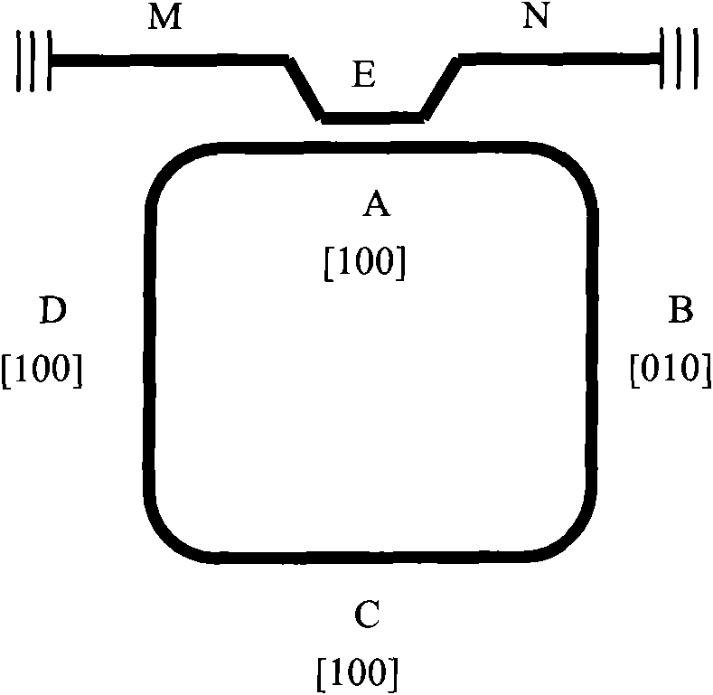
[0010] The specific implementation of the present invention will be described below by taking a GaP-based waveguide stimulated Raman scattering laser gyroscope as an example.

[0011] The schematic diagram of the principle of the all-solid-state laser gyroscope of the present invention is shown in the accompanying drawings. The laser gyroscope is composed of an input and output optical waveguide, a directional coupler and a ring optical resonant cavity, wherein the ring cavity optical waveguide is along the [100] or [010] direction. Assuming that the pump light is input from the X end of the optical waveguide, and the pump light is polarized along the [001] direction of the crystal, the pump light enters the A arm of the ring cavity waveguide through the directional coupler, and still maintains the polarization in the [001] direction, according to The selection rule of Raman scattering in the crystal, at this time, the polarization directions of Raman scattered light and optica...


PUM


Abstract

The invention discloses a laser gyroscope, relating to the laser technology, the optical technology and the inertia measurement technology. The existing laser gyro uses gas gain medium. The laser gyroscope uses a solid gain medium to replace the gas gain medium, thus realizing the all solidification of the laser gyro. However, compared with atoms or ions in the gas gain medium, atoms or ions in the solid gain medium are relatively static, thus causing strong competition among bidirectional optical field modes so as to further cause the instability of the optical field. In order to overcome the difficulties of the laser gyro using the solid gain medium, the laser gyroscope utilizes the optical stimulated scattering effect of pump light and the solid gain medium to provide gains for laser fields. As the laser fields spreading in different directions depend on the incident direction of the pump light, the pump light can be used for controlling the gains of the stimulated scattering light field spreading in different directions, thus realizing the stable output of the bidirectional laser mode of the solid laser gyro. The laser gyroscope is applicable to on-ship integration of the laser gyro.

Description

Technical field: [0001] The invention relates to laser technology, optical technology and inertial measurement technology. Background technique: [0002] Laser gyroscopes have been used for inertial speed measurement for more than 30 years. At present, laser gyroscopes have been commercially produced. His principle is based on the optical Signac effect. The rotation of the loop causes the frequency difference Δν of the traveling wave laser field propagating in the opposite direction in the ring laser gyroscope. The frequency difference is proportional to the rotational angular velocity. According to "Laser Gyroscope" written by Gao Bolong and Li Shutang, National University of Defense Technology Press (1984), has the following formula: [0003] Δv = 4 A Lλ Ω - - - ( 1 ) [0004] Among them, A represents the area of...

Claims


Application Information

Patent Timeline
IPC IPC(8): G01C19/66
Inventor 袁晓东叶卫民曾淳罗章刘肯朱志宏曾明
Owner NAT UNIV OF DEFENSE TECH
Why Eureka
Try Eureka