A tape machine control circuit for star a preset bell interlocking beside a tape machine

A control circuit and tape machine technology, applied in the field of electrical transmission, can solve problems such as potential safety hazards, cumbersome operation procedures, etc., and achieve the effect of preventing operation procedures

Pending Publication Date: 2019-01-25
鞍钢集团工程技术有限公司
View PDF0 Cites 2 Cited by
  • Summary
  • Abstract
  • Description
  • Claims
  • Application Information

AI Technical Summary

Problems solved by technology

The process of this operation method is cumbersome and has certain potential safety hazards. If the operator does not strictly abide by the operation p

Method used


Image

  • A tape machine control circuit for star a preset bell interlocking beside a tape machine
  • A tape machine control circuit for star a preset bell interlocking beside a tape machine
  • A tape machine control circuit for star a preset bell interlocking beside a tape machine

Examples


Embodiment Construction

[0025] The specific embodiments provided by the present invention will be described in detail below in conjunction with the accompanying drawings.

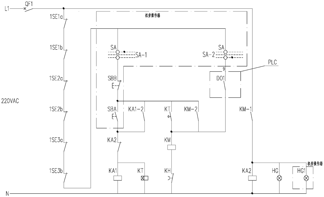
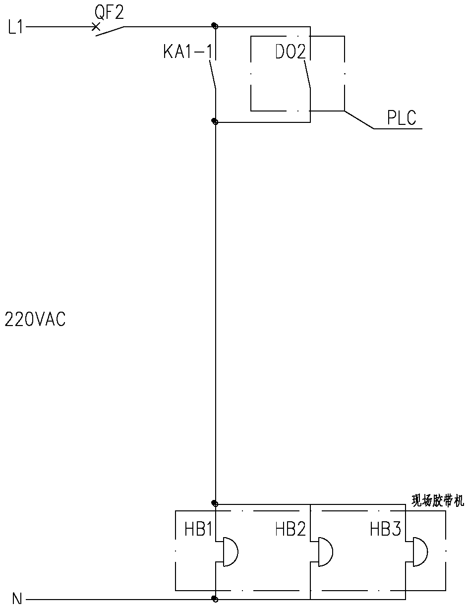
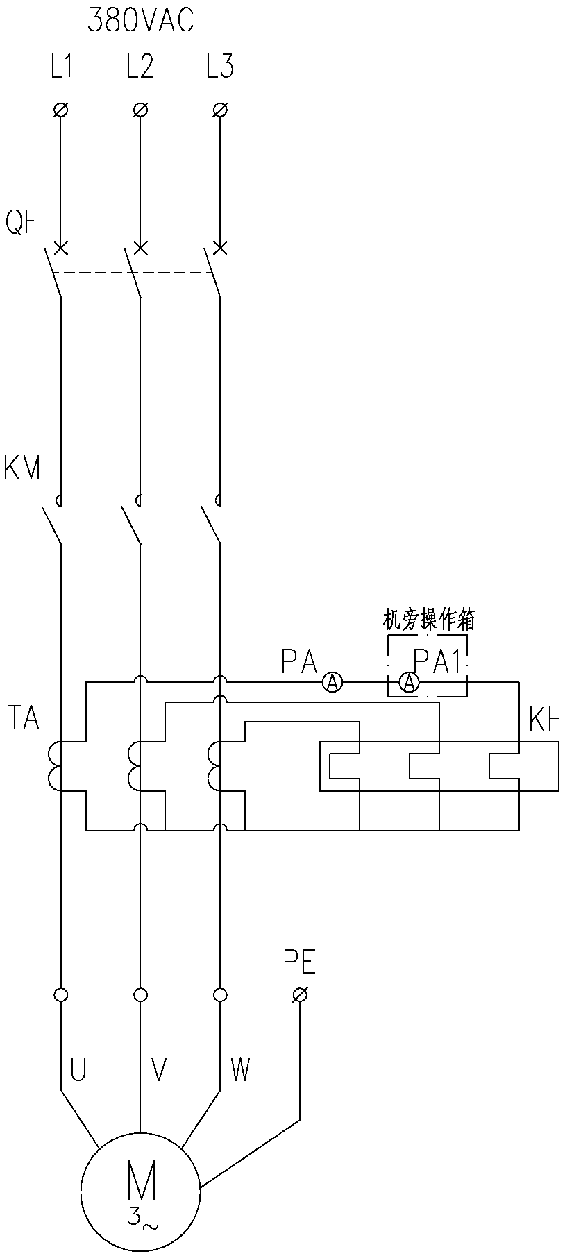
[0026] Such as Figure 1-2 As shown, a tape machine control circuit with an interlocking warning bell starting next to the machine includes a tape machine contactor KM, a thermal relay KH, and on-site warning bells HB1-HB3. It also includes machine-side / centralized selection switch SA, machine-side start button SBA, machine-side stop button SBB, first intermediate relay KA1, second intermediate relay KA2 and time relay KT. On-site warning bells HB1-HB3 are alarm bells commonly used in electrical control.

[0027] The machine side / centralized selection switch SA includes the machine side control bit SA-1, the upper end of the machine side control bit SA-1 is connected to the 220V power supply L1, and the lower end is in turn connected with the machine side stop button SBB normally closed point, and the machine side start button SB...


PUM


Abstract

The invention brings forward a tape machine control circuit for star preset bell interlocking beside a tape machine comprises a tape machine contactor KM, a thermal relay KH, a field preset bell HB, amachine-side/centralized selection switch SA, a machine-side start button SBA, a machine-side stop button SBB, a first intermediate relay KA1, a second intermediate relay KA2 and a time relay KT, wherein the tape machine contactor KM comprises a tape machine contactor, a thermal relay KH, a field preset bell HB, a machine-side/centralized selection switch SA, a machine-side start button SBA, a machine-side stop button SBB, a first intermediate relay KA1, a second intermediate relay KA2 and a time relay KT. Machine Side Control Bit SA of Machine Side/Centralized Selection Switch SA 1 is connecte to a 220v power supply l1, the lower end is sequentially connected with the normal closing point of the machine-side stop button SBB, SBA, the side startup button, is normally on, The normally closed point of the second intermediate relay KA2 is connected in series with one end of the coil of the first intermediate relay KA1 and the coil of the time relay KT, the normally open point of the time relay KT controls the coil of the tape contactor KM, and the first normally open contact KA1 of the first intermediate relay KA1 is connected with the coil of the time relay KT. 1 Control tape machine site preview bell HB. It realizes the function of automatic start-up of belt conveyor after early warning and delay, and avoids the safety accidents caused by misoperation when the belt conveyor starts beside the belt conveyor.

Description

technical field [0001] The invention relates to the technical field of electric transmission, in particular to a control circuit of a tape machine with an interlocking start warning bell next to the machine. Background technique [0002] As a belt-type material conveying device, the belt conveyor is widely used in coal mines, metallurgy, ports, chemical industry and other industries. It is the most commonly used transportation machinery for conveying bulk materials. The operation of the tape machine is relatively stable, the maintenance is relatively simple, and it is easy to realize automatic control and centralized control. In the industrial production process, how to ensure the efficient, safe and reliable operation of the tape machine is of great significance. In the past, safety accidents related to the tape machine occurred from time to time, especially when the tape machine started to run, safety accidents were more likely to occur. [0003] Since the general tape ma...

Claims


Application Information

Patent Timeline
IPC IPC(8): H02P25/16H02P1/16B65G43/00
CPCH02P1/16H02P25/16B65G43/00
Inventor 赵宝华刘伟高辉陈孝杰
Owner 鞍钢集团工程技术有限公司
Why Eureka
Try Eureka